Continue to Site

Welcome to EDAboard.com

Welcome to our site! EDAboard.com is an international Electronics Discussion Forum focused on EDA software, circuits, schematics, books, theory, papers, asic, pld, 8051, DSP, Network, RF, Analog Design, PCB, Service Manuals... and a whole lot more! To participate you need to register. Registration is free. Click here to register now.

Phase margin of opamp after post layout simulation

Status
Not open for further replies.

mordak

Member level 5
Joined
Mar 8, 2013
Messages
82
Helped
0
Reputation
0
Reaction score
0
Trophy points
1,286
Location
Neverland
Activity points
2,134
Hi,

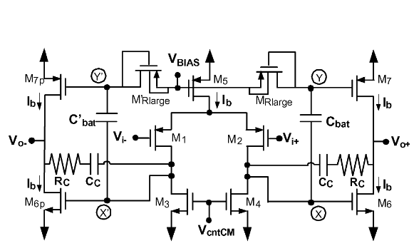
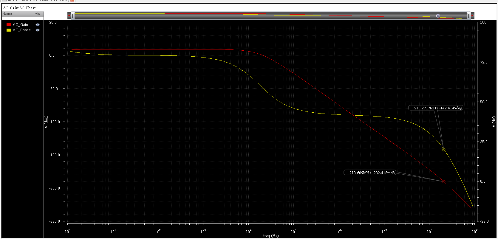
I have designed a class AB opamp and then drawn its layout. After extraction I run post layout simulation but saw that phase margin was degraded to 40 degrees. I was wondering if there is anyway I can trim the circuit to improve the phase margin, so I don't have to redraw the whole layout, or I need to start from scratch and design another opamp with higher phase margin so after layout I can get the desired PM.

Tnx
 

Yes - post the circuit and tell us how did you determine the margin?
 

Tnx guys for commenting. Below are the OTA structure and post layout frequency responce.


... I was wondering if there is anyway I can trim the circuit to improve the phase margin, so I don't have to redraw the whole layout

Can you afford to reduce the UGB - say to 100MHz - by enlarging the CCs ? This would probably upgrade the PM to about 60°.
 

Can you afford to reduce the UGB - say to 100MHz - by enlarging the CCs ? This would probably upgrade the PM to about 60°.
Unfortunately no, UGBW is critical for me so I can't sacrifice that.
 

Then I'd try the following changes:

1. reduce Cload
2. reduce Cbat & C'bat
3. play with the Rcs
 

Then I'd try the following changes:

1. reduce Cload
2. reduce Cbat & C'bat
3. play with the Rcs
I already tested them, thanks anyway. I guess there is no way but to take one step back and redesign it!
 

Probably this is tedious, but perhaps by comparison of the pre- and post-layout netlists you could try and find out, which layout influence (parasitic capacitance) shifts your non-dominant pole to a lower frequency (and so reduces your PM). This might even be helpful for the redesign.
 
  • Like
Reactions: mordak

    mordak

    Points: 2
    Helpful Answer Positive Rating
Status
Not open for further replies.

Similar threads

Part and Inventory Search

Welcome to EDABoard.com

Sponsor

Back
Top