Continue to Site

Welcome to EDAboard.com

Welcome to our site! EDAboard.com is an international Electronics Discussion Forum focused on EDA software, circuits, schematics, books, theory, papers, asic, pld, 8051, DSP, Network, RF, Analog Design, PCB, Service Manuals... and a whole lot more! To participate you need to register. Registration is free. Click here to register now.

Phase margin of 1st-order low pass filter

Status
Not open for further replies.

milvapp

Member level 5
Joined
Apr 17, 2010
Messages
88
Helped
3
Reputation
6
Reaction score
2
Trophy points
1,288
Location
chania greece
Activity points
1,882
Hi all,

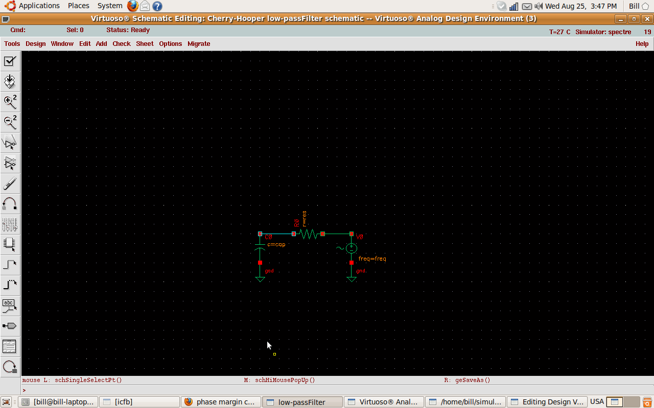
i have this LPF in Cadence.
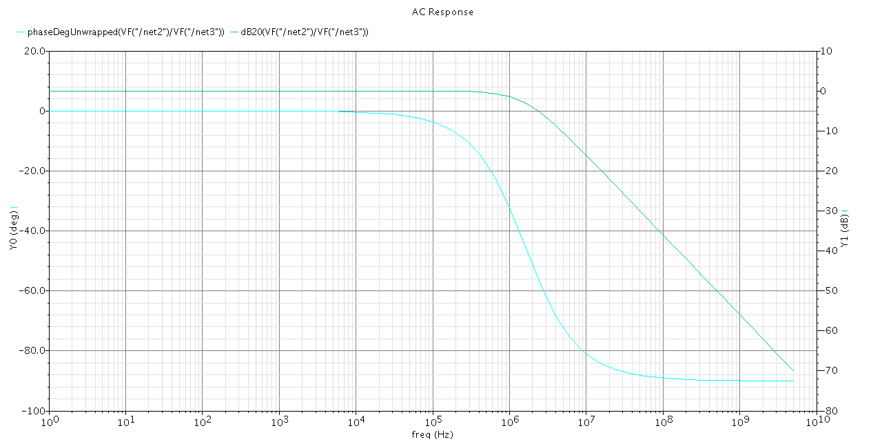
I want to check its stability so i want to calculate the phase margin.
However according to the ac simulation results of gain and phase,
i cannot figure it out.
Can someone help me?
I am quite new to this,so i would also like to know how to find the 3-db bw
in order to find the cutoff frequency.

res=500KΩ
cap=0.1pF

Thnx in advance,
Bill
 

A 1st order filter is a passive circuit with real poles and is unconditionally stable. I can't understand the question.

i would also like to know how to find the 3-db bw
For a low-pass, you have to find the frequency, where the gain has dropped by 3 dB related to the DC
respectively low frequency gain. You can read it from your diagram - or simply calculate it fg = 1/(2 pi R C),
about 3.2 MHz in your example.
 

    milvapp

    Points: 2
    Helpful Answer Positive Rating
FvM said:
A 1st order filter is a passive circuit with real poles and is unconditionally stable. I can't understand the question.

i would also like to know how to find the 3-db bw
For a low-pass, you have to find the frequency, where the gain has dropped by 3 dB related to the DC
respectively low frequency gain. You can read it from your diagram - or simply calculate it fg = 1/(2 pi R C),
about 3.2 MHz in your example.

Thank you.You really helped me a lot.I didnt know that 1st order are always stable.

Added after 4 hours 50 minutes:

Added after 1 minutes:

FvM said:
You can read it from your diagram - or simply calculate it fg = 1/(2 pi R C),
about 3.2 MHz in your example.

Another question.Acccording to theory -3db is at 3.2 MHz while if i follow the diagram
the -3db is at about 1.5MHz.Is this happening because of noise?
 

Acccording to theory -3db is at 3.2 MHz while if i follow the diagram
the -3db is at about 1.5MHz.Is this happening because of noise?
I didn't notice it. There's no noise involved in AC analysis, and it wouldn't change the filter's frequency
response. I have no explanation for the deviation. How many frequency points per decade respectively
octave did you specify for the AC analysis?. The -45 degree phase point should also correspond with the
low-pass pol frequency, but it doesn't.
 

Status
Not open for further replies.

Similar threads

Part and Inventory Search

Welcome to EDABoard.com

Sponsor

Back
Top