Continue to Site

Welcome to EDAboard.com

Welcome to our site! EDAboard.com is an international Electronics Discussion Forum focused on EDA software, circuits, schematics, books, theory, papers, asic, pld, 8051, DSP, Network, RF, Analog Design, PCB, Service Manuals... and a whole lot more! To participate you need to register. Registration is free. Click here to register now.

Phase Locked Loop Theory

Status
Not open for further replies.

Paul678

Newbie level 6
Joined
Feb 3, 2019
Messages
13
Helped
0
Reputation
0
Reaction score
0
Trophy points
1
Activity points
233
From this paper:

http://www.elenota.pl/datasheet-pdf/88472/National-Semiconductor/AN-1001

"When designing for a higher phase margin you trade off
higher stability for a slower loop response time and less
attenuation of the Reference Frequency."

Is this true for ALL PLLs?

And it would seem the converse is true with the loop
bandwidth, because a wider, higher loop bandwidth
gives you a faster acquisition time (Settling time), but
may make the loop less stable, and will attenuate the
Reference spurs less.

Thoughts?

 

Not a PLL expert here but yes control loop BW has those attributes you
mention.

This might be useful, still relevant after all these years.


Ok, thanks everyone. Banerjee's book is very good.

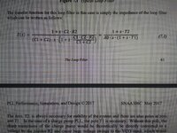
But is there a typo on page 42, in terms of where the zero and poles
are in transfer function 7.1, on page 41? (See attached pic) 20210711_174348.jpg
 
Last edited by a moderator:

Hi,

off-topic:
instead of shooting a photo (6.06MB for half a page) from a computer screen of a PDF (6,18MB for all 500 pages)
You could post a link: about 0.0001MB
or a screenshot with reduced picture quality (0.04MB jpg)

20210711_174348j.jpg


or a screenshot with perfect qualtiy (0.10MB png)

20210711_174348s.png


Remember this is a worldwide forum.. and there are many areas of low internet speed.

in post#5 now I edited your post so that there is a thumbnail, so not the whole 6MBytes need to be downloaded every time a member opens this thread.

Klaus
 
Ok, but if we want to find the "Zero", we have to find the value of "s" that makes the numerator 0, right?

So wouldn't that be s=-(1/T2)? And wouldn't the "Poles" in the denominator, be at zero, and s=-(1/T1)?

Am I missing something here? Or was this a typo?
 

It's a typo or inaccurate writing. Obviously he uses T as a notation which should correspond to the time constant of the zero or poles. And there is one pole at 0, an integrator.
 

It's a typo or inaccurate writing. Obviously he uses T as a notation which should correspond to the time constant of the zero or poles. And there is one pole at 0, an integrator.
So do you agree that in this case, the zero would that be at s=-(1/T2)?

And that the "Poles" in the denominator, would be at zero, and s=-(1/T1)?
 

Correct me if I am wrong, but it looks to me that for a PLL that I designed, that the open loop
unity gain frequency (0dB) appears to be the same as the closed loop bandwidth frequency.

And this frequency is also where the phase inflection point occurs, or where the open loop phase
margin is highest.

I believe Banerjee's book mentions this. But is this true for all PLLs, or just some of them?
 

It is true for any closed loop that if you have a unity feedback, like in a voltage follower opamp, the unity gain BW of the loop is about the same as the -3dB frequency of the closed loop response. In the PLL, for example a charge pump with zero in the loop, it is usually done so that the peak of the phase contributed by that zero comes at around the loop cross-over frequency.
 

Status
Not open for further replies.

Part and Inventory Search

Welcome to EDABoard.com

Sponsor

Back
Top