Continue to Site

Welcome to EDAboard.com

Welcome to our site! EDAboard.com is an international Electronics Discussion Forum focused on EDA software, circuits, schematics, books, theory, papers, asic, pld, 8051, DSP, Network, RF, Analog Design, PCB, Service Manuals... and a whole lot more! To participate you need to register. Registration is free. Click here to register now.

phase failure relay with over voltage and under voltage.

Status
Not open for further replies.

vishwa1

Newbie level 6
Joined
Apr 22, 2013
Messages
11
Helped
0
Reputation
0
Reaction score
0
Trophy points
1,281
Activity points
1,358
hi all,
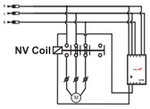
i have designed 3 phase under voltage and voltage solid state relay using op-amp.i am trying to add phase failure(single phasing protection) in that circuit,i am getting problem when any phase fails, still voltage is present in that phase.it does't decreasing.because of inductance between the phases.i have taken 3 phase line to input and output side.so my relay is not getting turn off...please tell me how to solve this problem.
thank you
 

right now i dont have the soft copy. tomorrow i ll post.

- - - Updated - - -

hi tpetar,
My circuit is similar to attached file.attached one is single phase, similarly i have designed for 3 phase.
 

Attachments

  • ci-4-over-voltage_1620.pdf
    54.1 KB · Views: 99

If you manufacture your own neutral and measure the phase to it, it must work. just connect three identical components to each phase and call their junction "local neutral". the current drawn by the components must not be too high or low, just enough for the measuring circuit. Say 3 X 100K resistors +-1%.
Frank
 

can you please send me the circuit.actually i tried lot on this.still its not getting off when i remove the phase.anyway thank you for the reply.
 

Phase det..png
If L1 disappears, there is no voltage for the top detector.
Frank
 

thanks chuckey,i will try this.later i will get back to u.........
 

"One of problems when phase loss that voltage between phase to phase did not decrease because of inductance between three coils in the motor. How do you resolve this problems?" .
I have attached the connection of my circuit,plz check the once,when phase fails,it wont decrease much hardly it decreases 30-40v.due to that my relay wont get off.I want to isolate or avoid that voltage And I have taken two phase voltage(any two) for control of high and lower voltage protection.

- - - Updated - - -

"One of problems when phase loss that voltage between phase to phase did not decrease because of inductance between three coils in the motor. How do you resolve this problems?" .
I have attached the connection of my circuit,plz check the once,when phase fails,it wont decrease much hardly it decreases 30-40v.due to that my relay wont get off.I want to isolate or avoid that voltage And I have taken two phase voltage(any two) for control of high and lower voltage protection.
 

Attachments

  • prf101.jpg
    prf101.jpg
    6.7 KB · Views: 98

AH!!! What you have here is a three phase rotary converter circuit, used for converting single phase to three phase. So the voltage you are measuring is actually being GENERATED by the motor. So you have to set you voltage trips very carefully or monitor the artificial neutral to earth.
To go over old ground. traditionaly 3 phase motors were monitored by means of the phase currents heating up a heater and tripping a mechanical contact that dropped out the contactor. They had a finite life as the bimetalic strip aged then they got unreliable. Then they invented the imbedded thermistor protection, measured the actual temperatures of the windings and with a detector box tripped the contactor when the windings got hot. These too have a finite life as the thermal stresses/vibrations in the windings broke the thermistors.
If you introduced a small transformer in series with each lead of the motor, say 230 v to 2 V @8A (for a motor running at 6A/phase), then each transformer would produce, about 230V X 6/8 = 180V. So put this winding in series with each monitoring lead, and you will have 412 + 180 ~600V. BUT if one phase was acting as a generator it would produce a current flowing out of the motor so the summed voltage would be 415-180 = 235V for that phase.
By the way your monitoring points should be right across the motor, else if a contact failed on the motor start contactor, you could not see it.
Frank
 

Imbalanced loads especially after a power failure can cause an unstable neutral which results in under/over voltage simultaneously.

Breaker faults for OVP/UVP must be very carefully designed and not a simple comparator without hysteresis nor memory nor time delay. This is what electro-magnetic and thermal designs included.
So you must defined these characteristics if you wish to emulate them in your simple relay driver. Emulating a delay is easy (RC) or an offset surge condition but defining those conditions for your system is not easy. Since we have no idea what it can handle.
 

Status
Not open for further replies.

Similar threads

Part and Inventory Search

Welcome to EDABoard.com

Sponsor

Back
Top