Continue to Site

Welcome to EDAboard.com

Welcome to our site! EDAboard.com is an international Electronics Discussion Forum focused on EDA software, circuits, schematics, books, theory, papers, asic, pld, 8051, DSP, Network, RF, Analog Design, PCB, Service Manuals... and a whole lot more! To participate you need to register. Registration is free. Click here to register now.

PCG signal display issue

Status
Not open for further replies.

MD_SHAHRUKH

Advanced Member level 4
Joined
Jun 5, 2017
Messages
103
Helped
4
Reputation
8
Reaction score
5
Trophy points
18
Location
Bangalore, India
Activity points
1,107
Hello everyone,
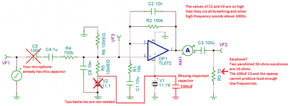
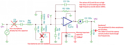
I have been working on an electronic stethoscope in which I have implemented one piezoelectric senor to hear the heartbeat, I get the heartbeat sound very clear to my earphone, but when acquiring that signal to ADC and try to plot the same, I am facing the issue of not so good signal, that means the plot rarely visualize the lub dub signals.

I have made many changes to the circuit, it enhances my sound signal but it is not at all improving my plot.

Should I get some digital IC into it? or analog circuit with ADC works fine?

1619444894041.png
 

In my post about filtering there is a thought that environment is high common mode (CM)
so might be best to place notch filter first so that you do not G up the CM and possibly
saturate the filter signal path. Also take G in it for noise cascade reasons.


Regards, Dana.
 

    MD_SHAHRUKH

    Points: 2
    Helpful Answer Positive Rating
The article says there are no breathing sounds above 2500Hz so maybe your cutoff frequency should be 2.5kHz. It is only 100Hz in your schematic.
I cropped your schematic to it is not as big as my neighborhood and made some corrections and notes.
 

Attachments

  • stethoscope circuit.png
    stethoscope circuit.png
    50.3 KB · Views: 181

    MD_SHAHRUKH

    Points: 2
    Helpful Answer Positive Rating
In my post about filtering there is a thought that environment is high common mode (CM)
so might be best to place notch filter first so that you do not G up the CM and possibly
saturate the filter signal path. Also take G in it for noise cascade reasons.
Okay, I'll try to add one notch filter of 50Hz.
--- Updated ---

The article says there are no breathing sounds above 2500Hz so maybe your cutoff frequency should be 2.5kHz. It is only 100Hz in your schematic.
I cropped your schematic to it is not as big as my neighborhood and made some corrections and notes.
Thank you for the correction, I have changed the capacitor value to 0.5nF to both C2 and C6. I have also put a Capacitor near the battery supply in the real circuit. And also I have not put 100nF near the microphone input, that was only for the simulation. And 2 batteries here are just in the simulation only not in the real circuit.

Thank you.
 
Last edited:

Hi,

I can see the heartbeat, but I can´t see any useful in the breathing. Can you give a short explanation what I have to look for?

Both are 200mV/div and 500ms/div ?

Klaus
 

    MD_SHAHRUKH

    Points: 2
    Helpful Answer Positive Rating
Take a closer look at the graph of breathing, If you are able to observe the pattern properly please compare to the image below, the tracheal sound at lungs expansion. (expanded time column)

WhatsApp Image 2021-04-30 at 4.45.26 PM.jpeg


I know it is not perfectly fine on my plot, but It is acceptable for now. But If you can suggest me few more corrections, I'll do the necessary updates, as tomorrow and the day after tomorrow is lockdown here. I can work more into it. And I am not doing the software part that is on RPi, so I can not answer what is done on RPi.

Thank you.
 

Hello everyone.
I have shown the circuit to the doctor today for approval of the circuit. The sound was perfect. Getting good sound in all the possible regions in the neck, chest, and back. The thing I got the recommendation from the doctor was the correct display of the signal to compare the neck sound with other chest sounds.

A small knowledge I want to share what the doctor explained to me was our lungs is like a cushion connected through a pipe, when we breathe in we will able to hear it from our neck but as we move our sensor to bottom of our chest the sound will disappear because there is no conduction of sound till the end. For a normal human, the sound heard from the neck and bottom chest must be mismatched. If the chest sound appears this means there is some conductive medium present in the lungs which can be liquid or solid, for the case of liquid it an infection like pneumonia or COPD, and solid like smoking lungs or pollution lungs.

I have one more issue left to resolve now, to give the signal to ADC, which I think I need to shift the signal a bit higher in order to capture in ADC. And plotting issue is still there because the breathing pattern is hardly received from other chest portions, so the comparison is a little time taking as we don't have patients to test.

Thank you so much EDA community, especially Klaus and Audioguru for making it possible before time.
 

Hi,
I have one more issue left to resolve now, to give the signal to ADC, which I think I need to shift the signal a bit higher in order to capture in ADC. And plotting issue is still there because the breathing pattern is hardly received from other chest portions, so the comparison is a little time taking as we don't have patients to test.
Some terminology issues.
When I read "shift the signal higher" --> I understand "add DC offset"
--> But I guees you mean to "amplify" the signal.

"Capture in ADC" is unusual, too. --> An ADC converts an analog signal into a digital value.

****
Regarding ADC input: Better to have a "small" input signal than a too big (and thus distorted) signal.
Indeed it depends about the analog signal dynamic ... and what resolution you need at the digital side.

Klaus
 

    MD_SHAHRUKH

    Points: 2
    Helpful Answer Positive Rating
The calculator in post #29 will allow you to determine, for the range and offset you need, the R values
for the OpAmp. Keep in mind their precision will determine accuracy.

Here is another version -


Regards, Dana.
 

The opamp output is now 2.0V to 3.0V with no input signal producing 2.5V.
I think the A to D input needs to be 0V to 5V with no input signal to the opamp at 0V.
Then the opamp should be a peak detector (rectifying) with DC offset.
 

    MD_SHAHRUKH

    Points: 2
    Helpful Answer Positive Rating
Please bare with me for the last time. There is noise issue in the circuit. I have used the circuit and placed it into the box where Display and battery and other components re connected.
1625486308216.png

And this place above which the vero board is placed:
[ATTACH" alt="1625487090791.png"]170582[/ATTACH]

The FFT of the output signal is showing two frequency one 1khz and 4khz. The circuit works fine when kept outside the box. but packing it inside is creating the issue.

What should I do here?
 

Attachments

  • 1625487090791.png
    1625487090791.png
    2.4 MB · Views: 149
Last edited by a moderator:

I dont see what should look like a good ground distribution technique for starters.

Ground in systems should be single point ground, where all grounds, where possible,
come to a common point. No daisy chaining grounds....minimize inductance in power
leads.


Manhatten style - http://www.worldofindie.co.uk/?p=900


1625489948941.png

Bulk capacitors, not all caps equal in ESR for the same C, Polymers and MLCC best -

1625489371223.png


Regards, Dana.
 
Last edited by a moderator:

The parts on your veroboard are much too far apart. Then their wiring picks-up 50Hz and its harmonics from nearby electricity.

I have made many preamplifiers on veroboard and they are so compact that without being inside a grounded metal case they produce no hum.
--- Updated ---

Before I did not see the changes you made to your schematic.
Now I see your TL072 dual opamp is powered from only 5VDC. But its minimum power supply voltage is 7V when it barely works. Many of them do not work when their input is only 2.5VDC.
It is a dual opamp and its second opamp is not disabled so it might be oscillating. Use a single opamp instead.
The TL07x opamps are fairly old and produce some noise. Newer audio opamps are much quieter.

Your new circuit also shows a transistor with NO input biasing so it will operate like a rectifier. The transistor is powered from an unregulated voltage that might have hum on it.

Your REG1117 regulator is missing the extremely important output capacitor shown on its datasheet so it is probably oscillating. You have its resistor values thousands of times higher than shown on its datasheet.
 
Last edited:

I think you are right I guess, I'll rebuild the circuit in more compact way. And take care of grounding as well.
There is no transistor in the circuit. The power supply for TL072 is coming from battery directly. It is 11.1 V.
I have also disabled the second opamp with proper circuit as per one document shared before.

I'll do suitable adjustment with all your suggestion and get back to you.
 

Today's schematic is the one you posted in post #14 four months ago and I corrected it in post #22.
Here are my corrections again:
 

Attachments

  • stethoscope circuit April.png
    stethoscope circuit April.png
    40.5 KB · Views: 137

Status
Not open for further replies.

Part and Inventory Search

Welcome to EDABoard.com

Sponsor

Back
Top