Terminator3
Advanced Member level 3
Hello all! I really confused about E-plane and H-plane after reading this datasheets. Here is screenshot of both datasheets (amitec and rfbeam):

Also i refer to this(1): **broken link removed** there is an image of patch antenna. And this(2): http://www.rfglobalnet.com/doc/the-basics-of-patch-antennas-0002
Also famous "E plane is the plane in which the electric filed is dominant".
As i understand E-plane is coincides with feeding line and perpendicular to radiating edges. Also E-plane perpendicular to patch itself.
Now i am looking at big patch array (white one): E-plane 7deg H-plane 25deg. But from image i can see that more elements is placed along H-plane, so H-plane must be 7 deg, and it is more likely that E-plane is 25deg.
Now green antennas:
Left one E-plane 50deg H-plane 80deg
Right one E-plane 50deg H-plane 40deg.
As we can see E-plane of both green antennas is 50deg, so it must be horisontal plane, as in-phase patches number is directly affect angle. But horisontal plane is H-plane from what i learned (http://www.antenna-theory.com/antennas/patches/antenna.php "Hence, the fringing E-fields on the edge of the microstrip antenna add up in phase and produce the radiation of the microstrip antenna.")
Here is final image that confuses things ever more:

(image from **broken link removed**)
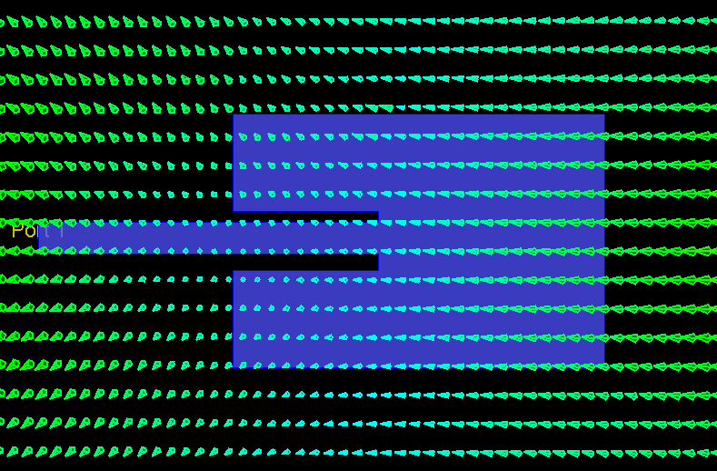
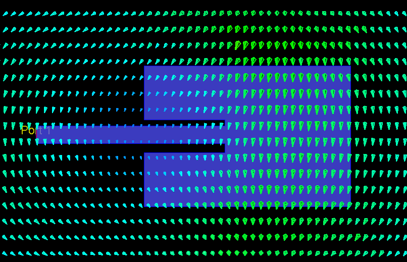
From this image we see that H-plane is perpendicular to feeding line, while E-plane is parallel with feeding line. Both planes perpendicular to PCB patch plane. If we look again at amitec and rfbeam images then E-plane and H-plane position does not match this image.
Please explain me what's wrong here?
Also i refer to this(1): **broken link removed** there is an image of patch antenna. And this(2): http://www.rfglobalnet.com/doc/the-basics-of-patch-antennas-0002
Also famous "E plane is the plane in which the electric filed is dominant".
As i understand E-plane is coincides with feeding line and perpendicular to radiating edges. Also E-plane perpendicular to patch itself.
Now i am looking at big patch array (white one): E-plane 7deg H-plane 25deg. But from image i can see that more elements is placed along H-plane, so H-plane must be 7 deg, and it is more likely that E-plane is 25deg.
Now green antennas:
Left one E-plane 50deg H-plane 80deg
Right one E-plane 50deg H-plane 40deg.
As we can see E-plane of both green antennas is 50deg, so it must be horisontal plane, as in-phase patches number is directly affect angle. But horisontal plane is H-plane from what i learned (http://www.antenna-theory.com/antennas/patches/antenna.php "Hence, the fringing E-fields on the edge of the microstrip antenna add up in phase and produce the radiation of the microstrip antenna.")
Here is final image that confuses things ever more:
(image from **broken link removed**)
From this image we see that H-plane is perpendicular to feeding line, while E-plane is parallel with feeding line. Both planes perpendicular to PCB patch plane. If we look again at amitec and rfbeam images then E-plane and H-plane position does not match this image.
Please explain me what's wrong here?