Continue to Site

Welcome to EDAboard.com

Welcome to our site! EDAboard.com is an international Electronics Discussion Forum focused on EDA software, circuits, schematics, books, theory, papers, asic, pld, 8051, DSP, Network, RF, Analog Design, PCB, Service Manuals... and a whole lot more! To participate you need to register. Registration is free. Click here to register now.

Passive filter for cleaning 240V line

Status
Not open for further replies.

fuuton

Advanced Member level 4
Joined
Jul 21, 2010
Messages
104
Helped
9
Reputation
18
Reaction score
2
Trophy points
1,298
Location
Pakistan, Rawalpindi
Activity points
1,881
Hi all,

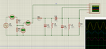
I recently designed a passive second order butterworth filter for 50Hz central frequency to be used on 240 mains voltage. The idea is to step down the voltage from 240 to 5V using a resistor divider. I made the circuit but when I connected it, the resistor divider just blew up. The rest of the circuit is fine.

I carried out simulation on proteus before hand to see if there is a large current flowing through any part but the current is around 360mA.

Please help me out. I cant figure out why the resistors are blowing up. Both resistors are rated at 1W.

Regards,
 

Attachments

  • filter.png
    filter.png
    133 KB · Views: 73

The two resistors total 480 ohms. Ohm's Law calculates their unloaded current at 240V/480 ohms= 0.5A. You show an extra 0.16A drawn by your circuit so the current in the 470 ohm resistor is 0.66A. it dissipates 0.66A squared x 470 ohms= 205W! No wonder the 1W resistor exploded.

That is why we use a transformer to step down an AC voltage that operates at a fairly high current.
 

You show polarised capacitors in your circuit diagram, these will not work on AC. You also show a 6 ohm load resistor, this is too low for you components, the current through them will over heat them.
So we know the circuit is connected to the mains, what would you like to get at its output?, voltage and current?
Frank
 

Hi Frank,

I want a voltage signal at the output. Can you recommend a guide to component selection for practical filter design?

Regards
 

Why can't you use a transformer?
In addition to what everyone else has explained already, the circuit that you are proposing is non-isolated and therefore a risk to both electrocution and fire.
 

Hi,

The transformer will take a lot of space and will increase the cost. I am tight on both aspects. I changed the component values and it is now consuming a lot less current. However, when I increase the divider values to 47k and 1k respectively, the value at the output is not 5V as per the formula. Its around 1.9V. Can someone please explain this?
 

I don't know about that but I would think that a transformer might be cheaper and even smaller than big power resistors, i have not thought this through but that is what I would think.
 

when I increase the divider values to 47k and 1k respectively, the value at the output is not 5V as per the formula. Its around 1.9V. Can someone please explain this?
If the two resistors have no load then with a 240V input their output is 5V. The load is parallel with the 1k resistor so it decreases the output voltage.
That is another reason we use a transformer instead of resistors. The output voltage from a properly made transformer barely drops when loaded.
 

Status
Not open for further replies.

Similar threads

Part and Inventory Search

Welcome to EDABoard.com

Sponsor

Back
Top