israel_Y
Member level 1

- Joined
- Feb 8, 2010
- Messages
- 34
- Helped
- 0
- Reputation
- 0
- Reaction score
- 0
- Trophy points
- 1,286
- Location
- The Netherlands
- Activity points
- 1,534
Please help,
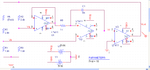
I am simulating resistance to frequency converter using Orcad Capture 16.5. Exact same schematic from the IEEE paper
"A High-Resolution, Linear Resistance-to-Frequency Converter" Kouji Mochizuki and Kenzo Watanabe 1996. the schematic is attached here.
The part where i face problem is when i vary the time duration in the transient analysis, the output varies unpredictably. (the Rval values that create oscillation vary): For example.
I simulated many times to see if i am making some mistake but unfortunately i couldnt detect it.
Please suggest why this problem occurs, is there initialization setting for analog simulation (i know there is digital initialization for flip flops).
I appreciate any idea/hunch/guess in advance. thank you
I am simulating resistance to frequency converter using Orcad Capture 16.5. Exact same schematic from the IEEE paper
"A High-Resolution, Linear Resistance-to-Frequency Converter" Kouji Mochizuki and Kenzo Watanabe 1996. the schematic is attached here.
The part where i face problem is when i vary the time duration in the transient analysis, the output varies unpredictably. (the Rval values that create oscillation vary): For example.
- for 800ms long simulation, Rval = 1 and Rval=66 ohm ONLY create oscillation while the rest are flat
- for 2sec long simulation Rval = 1 and Rval=51 ohm create oscillation while the rest are flat
I simulated many times to see if i am making some mistake but unfortunately i couldnt detect it.
Please suggest why this problem occurs, is there initialization setting for analog simulation (i know there is digital initialization for flip flops).
I appreciate any idea/hunch/guess in advance. thank you
Attachments
Last edited by a moderator:

