Continue to Site

Welcome to EDAboard.com

Welcome to our site! EDAboard.com is an international Electronics Discussion Forum focused on EDA software, circuits, schematics, books, theory, papers, asic, pld, 8051, DSP, Network, RF, Analog Design, PCB, Service Manuals... and a whole lot more! To participate you need to register. Registration is free. Click here to register now.

Parameters required to find a replacement for an inductor...

Status
Not open for further replies.

powersys

Advanced Member level 1
Joined
Nov 29, 2005
Messages
439
Helped
3
Reputation
6
Reaction score
2
Trophy points
1,298
Activity points
4,981
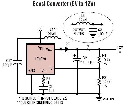
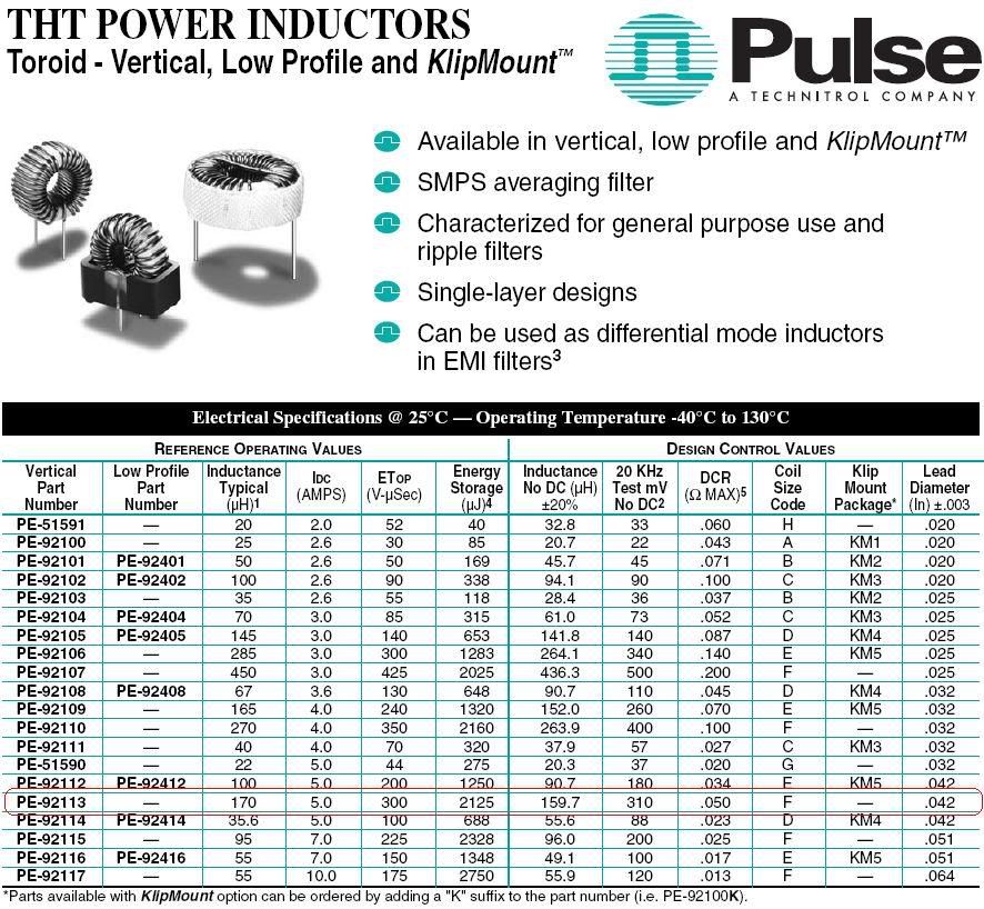
I wish to build a boost converter using LT1070 as shown in the 1st figure. The power inductor suggested by Linear Technology is PE-92113 from Pulse Engineering (pls refer to 2nd figure). Unfortunately, PE-92113 is not available in local market. Therefore, we wish to get a replacement for the inductor. However, as shown in 2nd figure, there are many parameters/specifications that describe an inductor. Besides the inductance value, which parameters are important and required to find an inductor (e.g. manufactured by C&D Technologies) that will match the performance of PE-92113 as close as possible?

By the way, what is the difference between the following two inductances:
[3rd Column] Inductance Typical (uH)
[7th Column] Inductance No DC (uH) +/-20%
And, why the inductance value shown in 7th column is lower than that of 3rd column?

Thanks

LT1070Boost.jpg


pe-92113.jpg
 

Re: Parameters required to find a replacement for an inducto

Besides inductance, you should look for DC resistance, core loss, nominal current, saturation current.

Sometimes, you get the energy storage capability. From that you can get the DC current, because E=0.5*L*I²
In your case, L=170uH, so E=0.5*170*5²=2125 uJ.

DC resistance is important for your power loss. DC current is generally given for 40C temperature rise of the inductor. That may not always be optimal for a design. So choose it based on the DC resistance and how much power you can afford to lose in the inductor. But always make sure that you do not exceed the saturation current.

Core loss depends on switching frequency, ripple current and core material. That loss adds to the DC resistance loss and rises the temperature of the inductor. Generally you will not get the core type (unless you design your own inductor), but a core loss factor should be given. Use that to estimate the core losses.
In the end, if you know the total inductor loss, use that to calculate the temperature rise. From the datasheet calculate the power dissipation for the DC curren given:
P=R*I²
Then you know that this produces 40C rise (by the way, this is a recommended limit, try not to exceed this temperature rise). Then you know that the thermal resistance is:
Rth=40/P
Substitute your calculated power (DC+core loss) in that equation and find out your actual temperature rise.
If the core loss factor is not given (it rarely is), then make sure the DC resistance is low enough such that the you will still have some room for the core loss. Start by allowing about 30% of the total power for core loss. If the temperature rise is much higher than expected, you need to select another inductor. With the LT1070, running at 40kHz, I would not worry too much about core loss.
In your case, P=0.05*5²=1.25W, Rth=40/1.25=32C/W If the current is 2A in the inductor (that is about right for your 5/12V@1A boost), then your DC power loss is:
Pdc=0.05*2²=0.2W. That represents about 1.6% of the total boost output power. Normally, you would allow 2% for losses in magnetics. So probably that is what the designer had intended. In that case, 2% of 12W is 0.24W and so the core loss was 0.04W. Compared to the DC loss, that is 0.04/0.2=20%. Sounds about right.

As stated above, nominal current given is actually that DC current that produces 40C rise. A first quick check will tell you if the inductor is good enough. Then you get into the other details.

Saturation current is usually give as that current at which the inductance drops by 10% of the nominal. Stay away from this current level, including current peaks, to avoid core saturation. Should that happen, the inductor becomes basically just a wire and the current through it can increase so fast that the regulator's current limit circuit cannot switch off the transistor and that can lead to failure.

So, choose an inductor that has the same inductance, same or lower DC resistance, lower core loss, same footprint (if important), same or higher saturation current.

The inductance drops with increasing DC current due to saturation. Without any DC, you get the highest inductance. However, for the powdered iron cores, the inductance drops more gradually with increasing DC current, because of the inherent distributed air gap of the core material.
Inductance in column 3 is the typical value you would measure when you buy an inductor. In column 7 is the actual value they check in production to pass or fail the part. That is done under certain conditions of excitation, so the two values can be different.
 

    powersys

    Points: 2
    Helpful Answer Positive Rating
Status
Not open for further replies.

Part and Inventory Search

Welcome to EDABoard.com

Sponsor

Back
Top