Continue to Site

Welcome to EDAboard.com

Welcome to our site! EDAboard.com is an international Electronics Discussion Forum focused on EDA software, circuits, schematics, books, theory, papers, asic, pld, 8051, DSP, Network, RF, Analog Design, PCB, Service Manuals... and a whole lot more! To participate you need to register. Registration is free. Click here to register now.

paralleling switching converters

Status
Not open for further replies.

m2babaey

Junior Member level 2
Joined
Oct 18, 2012
Messages
21
Helped
0
Reputation
0
Reaction score
0
Trophy points
1,281
Activity points
1,445
Hi
Assume I have 2 Switching mode power supplies
For example 2 flyback 400V/12V converters with 5A nominal output current. These power supplies do not have current limit protections

My load (12V) requires a 10A power supply
What happens if I parallel my two SMPSes?
What should I take care about?
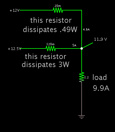
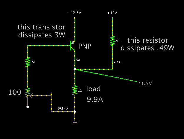
I know that in reality, the output voltage of my 2 converters are not exactly equal

I know the concept for paralleling transformers. Current may circulate through transformer windings and there may be problems with load sharing
For switching converters, I guess The converter whose voltage is a bit greater than the other, will supply all the current to load and will get damaged?
What do you think?
What are your suggestions?
 

The 2 supplies will not share load equally. Over time this inequality may increase and the one sharing the larger share of the current will burn.

How about connecting the 2 supplies in series to create a 24V supply and then using a 24V to 12V switching converter? I'm not sure what'll happen then.
 

Balancing series resistors seem to be the only applicable soultion.
 
Balancing series resistors seem to be the only applicable soultion.
Thanks
1. Could you please explain more? How should I decide about the resistor values for 2 existing converters?

2. What if I want to construct parallel-able converters, how can I design it to work for all conditions?
I prefer not to waste too much power

maybe I should measure the current and reduce the duty cycle for the converter with higher current
 

Suitable balancing resistor values depend on the SMPS characteristic, voltage acuracy and overload behaviour, I think. 50 or 100 mV voltage drop might be reasonable.

Power supplies with clear current limiting possibly don't need it at all. A particular problem arises if the SMPS have stutter overload shutdown.

Ideally, the control circuit would be paralled at at node that allows perfect load sharing, e.g. the FB terminal of the PWM chip.
 

If one supply is 0.6V higher than the other, then you could insert a diode (rated to carry 5A).

Or suppose one supply is 0.5V higher than the other (at 5A)...

Then a dropping resistor must drop 0.5V.

If current is 5A, then the resistor should be 0.1 ohm. It must dissipate 2.5W.

There's a chance you will want to install a resistor in both supplies (perhaps to fine-tune them). Or maybe a length of resistive wire, where you will tap at different points until you obtain balanced distribution of currents.

Screenshot of sample setup:

3445664500_1354994207.png
 

It's not easy to find/fabricate custom resistors at such a low ohm value.

A high-power transistor will do the job.

Screenshot:


A PNP type is needed. An NPN will be impossible to bias sufficiently (unless you rearrange things so it is in the low side of the power loop).
 

Status
Not open for further replies.

Similar threads

Part and Inventory Search

Welcome to EDABoard.com

Sponsor

Back
Top