Continue to Site

Welcome to EDAboard.com

Welcome to our site! EDAboard.com is an international Electronics Discussion Forum focused on EDA software, circuits, schematics, books, theory, papers, asic, pld, 8051, DSP, Network, RF, Analog Design, PCB, Service Manuals... and a whole lot more! To participate you need to register. Registration is free. Click here to register now.

Parallel DC-DC Variable Voltage BUCK Converter

Status
Not open for further replies.

asking

Full Member level 5
Joined
Sep 21, 2010
Messages
279
Helped
6
Reputation
12
Reaction score
6
Trophy points
1,298
Activity points
3,377
Hello again,

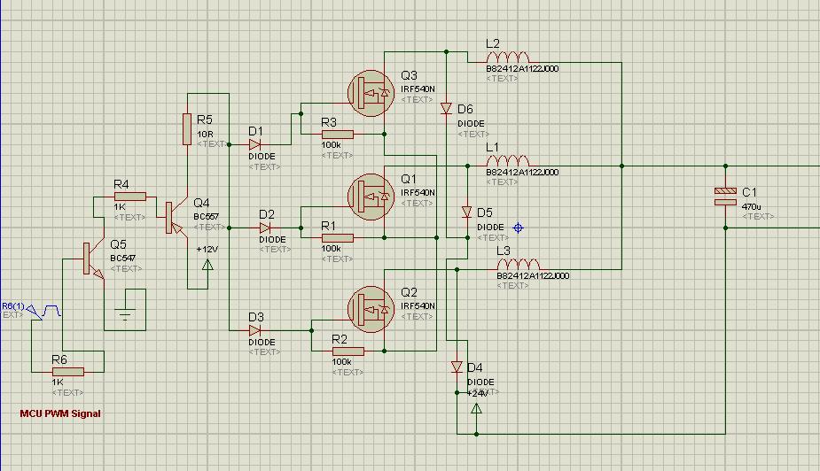
With reference to this post, i came to know about importance of inductor, but now issue is with Current capacity. I need 15 AMP 100uH Inductor which is not available for me. Instead i got 6A 100uH 3 Coils instead and i have create circuit below in which i have place 6AMP 3x DC-DC Buck converters parallel and PWM Common signal. In this way i can have high frequency with less switching losses. Suppose i switch 3 of them @ 500 KHZ total efficiency i will get will be of 1.5MHZ with lesser switching losses. This is what i think, pls guide me if i m wrong. thanks


What you describe will work, with adjustments. (Your schematic shows mosfets which are not connected to ground or the power supply.)

You might want to consider interleaving 3 converters, instead of operating them in unison.
My simulation illustrates a triple interleaved buck converter.
10 kHz, 23% duty cycle.


Each coil carries 5.9 A maximum (give or take). Continuous conduction mode with 31% current ripple.

Notice that the supply does not have to provide more than 6A this way. Whereas, if you were to run the converters in unison, the supply would need to provide 18A at peak.
 
  • Like
Reactions: asking

    asking

    Points: 2
    Helpful Answer Positive Rating
What you describe will work, with adjustments. (Your schematic shows mosfets which are not connected to ground or the power supply.)

You might want to consider interleaving 3 converters, instead of operating them in unison.
My simulation illustrates a triple interleaved buck converter.
10 kHz, 23% duty cycle.


Each coil carries 5.9 A maximum (give or take). Continuous conduction mode with 31% current ripple.

Notice that the supply does not have to provide more than 6A this way. Whereas, if you were to run the converters in unison, the supply would need to provide 18A at peak.

Yes, Actually i forgot to connect to ground in the schematic. BTW screenshot you provided is from which software ? is there any software other than proteus for simulating analogue circuits ? you information would be helpful to me. Thanks...
 

It's Falstad's interactive animated simulator. It has many convenient features built in.

falstad.com/circuit

If you click the link below, it will open Falstad's website, load my schematic, and run it on your computer.

https://tinyurl.com/crex9yw

The clocks each need to be altered individually.

In real life you will need to make a driver circuit, which will distribute on-off signals to the switching devices, and adjust the frequency, duty cycle, etc.
 
  • Like
Reactions: asking

    asking

    Points: 2
    Helpful Answer Positive Rating
Interleaving might sound like a challenge to build. You must send independent on-off gate signals to each converter.

However in this case interleaving will be easy. Since the duty cycle is short, one converter turns off before the next one turns on.


Frequency and duty cycle are adjustable at the clock generator.

This method could not be used if the duty cycle is long. In that case the converter On-times have to overlap.
 
Hi asking

I think the idea of Bradtherad is so fascinating but besides these issues , it might be expensive and larger . if price or compact designing is not one of the important factors it is so brilliant . but if it is an issue , then a master/slave feedback might cover the aim as well .
Best Wishes
Goldsmith
_______________________________
Hi Bradtherad
Let me confess that your circuit in your post #5 is very interesting to me and i want build it and see the result because it is one of the simplest bit shifters that i've ever seen . thanks for that .

Best Regards
Goldsmith
 
  • Like
Reactions: asking

    asking

    Points: 2
    Helpful Answer Positive Rating
Hi Bradtherad
Let me confess that your circuit in your post #5 is very interesting to me and i want build it and see the result because it is one of the simplest bit shifters that i've ever seen . thanks for that .

Best Regards
Goldsmith

Thanks, any affirmation is great to hear.

If you make a million dollars marketing it, I will be happy with 10% of the profit.

After some more experimenting, I find that by substituting NAND gates for the AND gates, it allows duty cycles ranging from 67 to 99 percent.
 
Status
Not open for further replies.

Similar threads

Part and Inventory Search

Welcome to EDABoard.com

Sponsor

Back
Top