Welcome to our site! EDAboard.com is an international Electronics Discussion Forum focused on EDA software, circuits, schematics, books, theory, papers, asic, pld, 8051, DSP, Network, RF, Analog Design, PCB, Service Manuals... and a whole lot more! To participate you need to register. Registration is free. Click here to register now.
Hi,
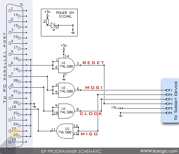
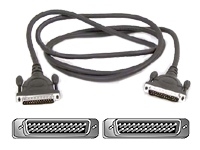
You have to use a 25 pin DB25 male connector as shown in your picture at one end of the cable, which will be plugged into the printer port of PC,which is normally a DB25 female connector. You should wire up the circuit shown in your earlier diagram as part of the cable. Inorder to connect the cable to 89S52 board, you need not use a DB25 connector, instead you can use a simple 6 pin connector. By doing so, you can also avoid the possibility of connecting the wrong end to PC.
The picture shown is a bit confusing since it looks like a simple cable with DB25 male connectors at both ends and it does not show where the circuit components are assembled.
Regards, Laktronics
Hi,
Standard parallel port cable will have many more wires, eg. 8 Nos for data bits, Ack, Busy , ground and so on. You have to use only specific five wires (including ground)shown in your circuit. Vcc is from your board. If you are mounting the AND gate as a part of your board, you can just connect these five wires to your board directly and be done with it.
Regards,
Laktronics
P.S.
Standard printer cable does not have any logic circuit as a part of it. It has only simple wires connected between pins. If you mount the logic circuit of your programmer cable on your S52 PCB, you can also use cable having only few wires, but it will not be an ISP cable in the true sense. People therefore mount this logic as a part of the cable, inside the hood of the connector.
Laktronics
This site uses cookies to help personalise content, tailor your experience and to keep you logged in if you register.
By continuing to use this site, you are consenting to our use of cookies.