Continue to Site

Welcome to EDAboard.com

Welcome to our site! EDAboard.com is an international Electronics Discussion Forum focused on EDA software, circuits, schematics, books, theory, papers, asic, pld, 8051, DSP, Network, RF, Analog Design, PCB, Service Manuals... and a whole lot more! To participate you need to register. Registration is free. Click here to register now.

P-Mosfet heating problems

Status
Not open for further replies.

Cval

Junior Member level 1
Joined
Jan 23, 2012
Messages
19
Helped
0
Reputation
0
Reaction score
0
Trophy points
1,281
Visit site
Activity points
1,442
Hello,
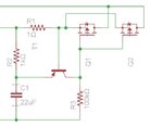
I am having an issue with my PCB. The circuit is a current limiting circuit in which the limit threshold is controlled by R1. The output is to a motor spinning a wire which must stall at the specified current in order to prevent damage. The P-Mosfet is heating up when the motor is at or close to the stall limit. The heat isn’t damaging the FET, but it is affecting the other components (PNP) causing the specified stall current to drop from ~.6A to ~.3A.

I believe this is happening because the FET is not fully off as the motor is still drawing ~.6A when the stall limit is reached, which is what it was designed to do. I can change the FET if there is a spec that will improve the thermal stability, would this have to do with the FET’s switching characteristics? Would it be better to have a faster or slower switching time? Should I find a PNP trans that will be less effected by heat?
Thanks,

R1=1ohm
R2=1k
R3=100k
R4=82ohm (for a potentiometer)
C1=22uF
T1=P-Mosfet (**broken link removed**)
U1=PNP Trans (**broken link removed**)



CLC.jpg
 

The power dissipated by the MOSFET is determined by the limit current times the voltage drop across it. That is unaffected by the switching speed of the transistor and won't change with a different transistor. And all BJT transistors have the same temperature coefficient. A couple solutions are to change the circuit to shut off the current (using a latch or fold-back limit circuit) when the limit is reached, or mount the MOSFET on a separate heat-sink away from the circuit so it's temperature rise has no effect on circuit temperature.
 
Last edited:

So if I take the voltage drop across the circuit while the motor is stalled I get 6V, and with a 0.6A current limit the FET will be dissipating 3.6W? That seems pretty low, but the FET is getting very hot.
 

So if I take the voltage drop across the circuit while the motor is stalled I get 6V, and with a 0.6A current limit the FET will be dissipating 3.6W? That seems pretty low, but the FET is getting very hot.
A FET not on a heat sink can only reliably dissipate about a watt or so thus 3.6W will definitely make it very hot and will likely zap it if it dissipates that amount for a long period of time.
 

I calculated 175C-25C = 150C (Tjmax - Ambient). Then (150C)/(50C/W) = 3W (Heat limit/Rja) Max power dissipation for the FET before reaching the critical limit in ambient air. If I were to add another fet in parallel wouldn't that half the 3.6W power dissipation to 1.8W? Would this be more effective than a heat sink? Thanks

Edit, If i could find the Rcs for the FET i could calculate the difference.
 
Last edited:

I put two of the same FETs in parallel and am getting strange results. both fets will heat up initially then one seems to turn off and the other one takes the grunt of the load. Any ideas as to why this is?
 

I put two of the same FETs in parallel and am getting strange results. both fets will heat up initially then one seems to turn off and the other one takes the grunt of the load. Any ideas as to why this is?
The two transistors have different threshold voltages due to normal manufacturing variations (look at the data sheet), thus the one with the lower threshold voltage will take more of the load. You can add small source resistors to help balance the load but that would lower than output voltage due to normal motor current. I think a small heat-sink is your best solution.
 

Due to size constraints, adding a heat sink may be difficult. Attached is some temperature data from the fets at stall for 1 minute. This seems much improved; however, the capacitor is having a weird affect when both FETS are used, the stall current will drop and the motor makes a strange noise. With one fet the system works fine.

I had to disconnect the capacitor to do the test. My spice simulation works fine with both fets.


tmp.jpg

- - - Updated - - -

Here's the schematic, 9V input.

cb.jpg
 

The noise is likely oscillation in your limit circuit.

Your Spice simulation works fine because both MOSFETs have identical characteristics. That doesn't happen in real life.
 

Status
Not open for further replies.

Similar threads

Part and Inventory Search

Welcome to EDABoard.com

Sponsor

Back
Top