Continue to Site

Welcome to EDAboard.com

Welcome to our site! EDAboard.com is an international Electronics Discussion Forum focused on EDA software, circuits, schematics, books, theory, papers, asic, pld, 8051, DSP, Network, RF, Analog Design, PCB, Service Manuals... and a whole lot more! To participate you need to register. Registration is free. Click here to register now.

P MOSFET as a switch. LTSPICE simulation

Status
Not open for further replies.

svia

Member level 3
Joined
Feb 7, 2008
Messages
61
Helped
10
Reputation
20
Reaction score
9
Trophy points
1,288
Activity points
1,774
I need some help to understand how the following circuit works.

I get that the MOSFET N when Vgs> Vgs_thereshold, Vdrain= Vs

But how does a MOSFET P works, in simplified words, as a switch?

And how this entire circuit work?
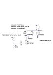
Output.jpg

I can't get it simulating when using pulse signal and transient in LTSPICE. I should have some setup wrong, any clue?

Thanks
 
Last edited:

What does it mean "can't get simulating" LTSpice simulation don't work, or simulation is not like you want?
I am not sure what you would like to get, but in your circuit you should connect any resistor between Vout and GND - it could be very high - 10^12 or more, to allow LTSpice to calculate anything, and then see what happened.
From the first point of view I am not sure if there is diode present in FQT3P20 model, to you could see that transistor could be wrong polarised. I am not sure if you should connect S to Vout not Vpmos
 

For starters it looks like you have the FET upside down
and it will act pretty much like a diode.
 

Status
Not open for further replies.

Part and Inventory Search

Welcome to EDABoard.com

Sponsor

Back
Top