Gary_SMi
Junior Member level 1
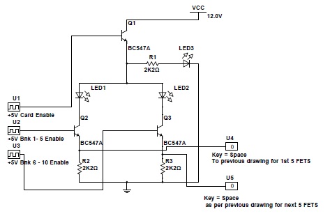
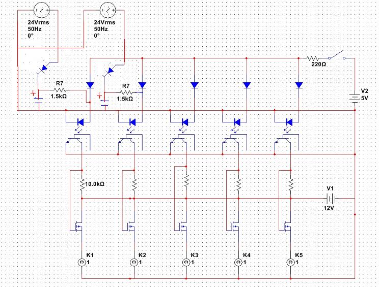
Hello, I have 5 x 8A mosfets that need to drive individual loads. They need to be triggered in 2 ways, 1.) all 5 triggered together from 1 microcontroller output or 2.) They need to be triggered individually from 24Vac plc outputs. Have tried as attached but produces undesirable results and the fets dont trigger correctly. The 24V section on the drawing is duplicated throughout the other channels. Can anyone possibly assist where I am going wrong with this? Thanks.


")