Continue to Site

Welcome to EDAboard.com

Welcome to our site! EDAboard.com is an international Electronics Discussion Forum focused on EDA software, circuits, schematics, books, theory, papers, asic, pld, 8051, DSP, Network, RF, Analog Design, PCB, Service Manuals... and a whole lot more! To participate you need to register. Registration is free. Click here to register now.

Overshoot/Ringing

Status
Not open for further replies.

jbec

Newbie level 5
Joined
Sep 22, 2019
Messages
8
Helped
0
Reputation
0
Reaction score
0
Trophy points
1
Activity points
62
Hi,
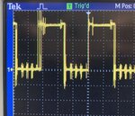
I have designed and tested a class d amp. I have problems with ringing and spikes, I don't think it is overshoot because I have dead-time. I am designing for an H bridge but I tested with a half-bridge first. The output of the MOSFETs are shown in the image. Same output with the driver outputs

Switching frequency is 30 KHz. Using ir2110 with irfb4019. Bootstrap capacitor as diode are 0.1uF and UF4007.
The driver is powered with 5v and 12 v and MOSFETs with 15v. Can someone please help me out?
 

Attachments

  • 3E13D0FD-3299-462E-854C-59907951B52B.jpeg
    3E13D0FD-3299-462E-854C-59907951B52B.jpeg
    1.6 MB · Views: 99

Hi,

If you really need good assistance, then it's urgent to provide
* schematic and
* PCB layout with exact locations where you connected the scope (both: GND and signal)

I don't think it is overshoot because I have dead-time.
With dead time you prevent from through shoot / cross conduction.

My first idea is, that most of the overshoot/ringing comes from measurement errors.
But for the multiple ringing pieces during Low phase I have no explanation for now. (Missing informations)

Same output with the driver outputs
Don't know what this means.

In case you want good audio 30kHz is a bit low frequency.

Connect a suitable load to get better measurement results (less than 100 Ohms)

Klaus
 

1. Add ceramic decoupling capacitors close to the bridge
2. If the FETs still overshoot, add an RC snubber across each drain-source. A reasonable value to start with would be 1 Ohm in series with 4.7nF.
 

    Easy peasy

    Points: 2
    Helpful Answer Positive Rating

    jbec

    Points: 2
    Helpful Answer Positive Rating
Hi, thank you for your suggestions. I found out what wa the problem for the overshooting/ringing. It was the deadtime generated from the RC Xor gate network. I changed the circuit to a resistor diode capacitor circuit and it helped a lot. I'm having some more problems, the low side output waveform is measuring a peak to peak of 18v and not 12v. Can anyone assist me with this problem.
 

Attachments

  • F0008TEK.JPG
    F0008TEK.JPG
    88.6 KB · Views: 103

The pk-pk includes the undershoot peak you see in your waveform.

Do you have a picture of prototype you are working with, and a schematic ?


Also scope probing methods quite important to getting accurate signal envelopes.


Also capacitor technology used for bypassing very important, eg. ESR vs Frequency

1594546513892.png


Regards, Dana.
 

As long as the measured gate voltage waveforms isn't exceeding transistor maximum ratings, you don' even need to determine if it's real or a probing artefact. I guess the latter.
 

Status
Not open for further replies.

Similar threads

Part and Inventory Search

Welcome to EDABoard.com

Sponsor

Back
Top