Continue to Site

Welcome to EDAboard.com

Welcome to our site! EDAboard.com is an international Electronics Discussion Forum focused on EDA software, circuits, schematics, books, theory, papers, asic, pld, 8051, DSP, Network, RF, Analog Design, PCB, Service Manuals... and a whole lot more! To participate you need to register. Registration is free. Click here to register now.

oven power supply without output voltage

Status
Not open for further replies.

erchiu

Member level 5
Joined
Apr 7, 2012
Messages
93
Helped
2
Reputation
4
Reaction score
1
Trophy points
1,288
Location
Rome - Italy
Activity points
2,082
Hi everyone.
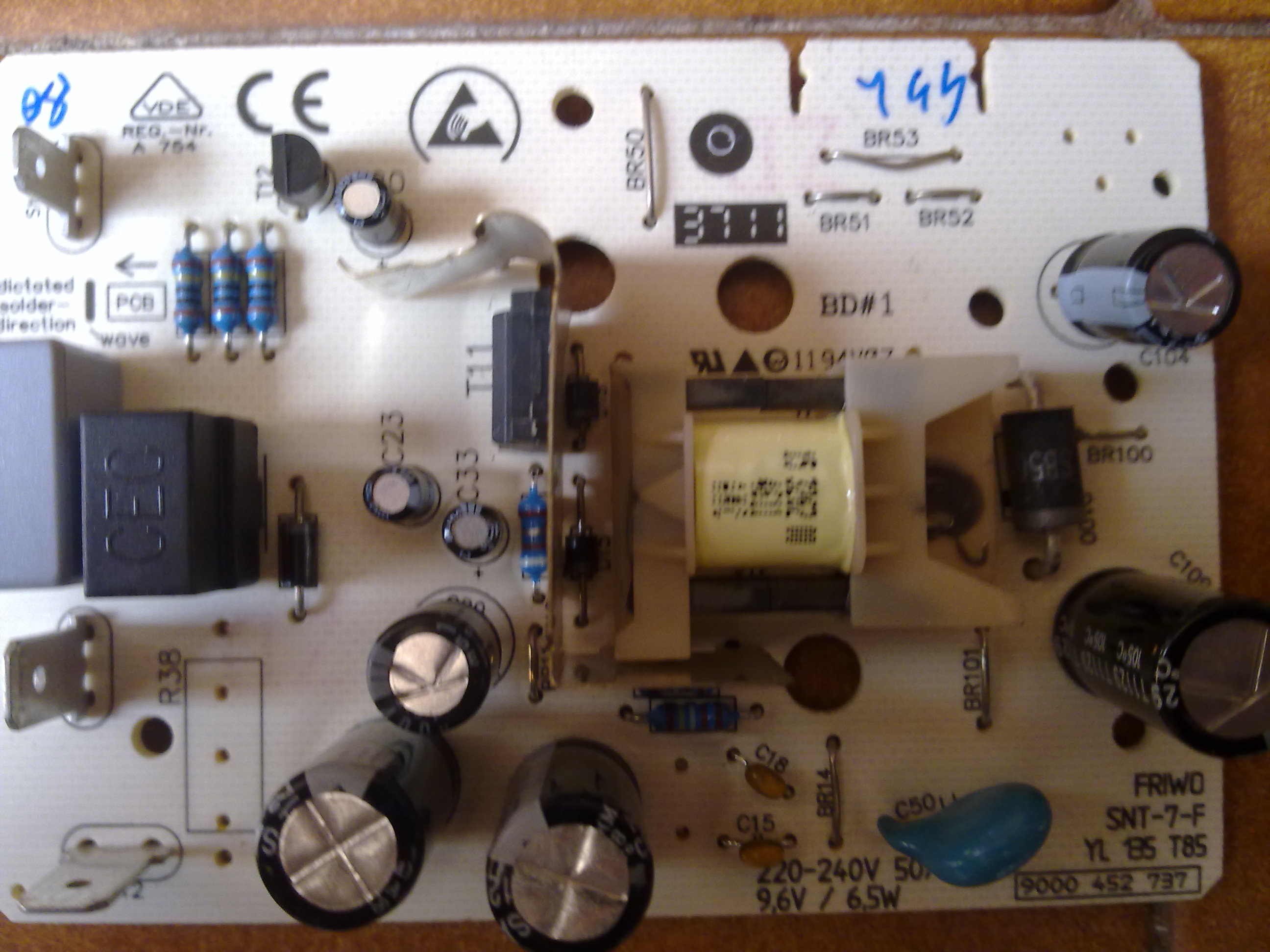
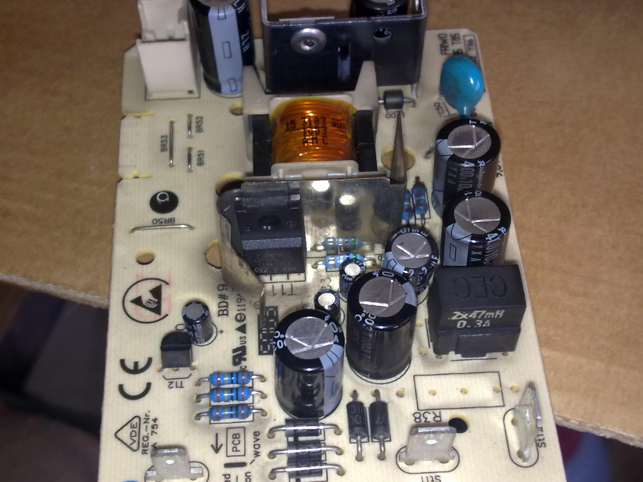
i have an oven with an electronic board that not working
this oven have three electronic boards.
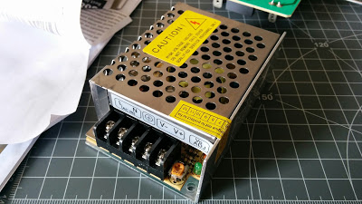
1) power supply
2) power (with relais)
3) control (with buttons and display)
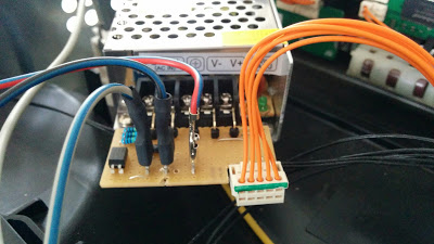
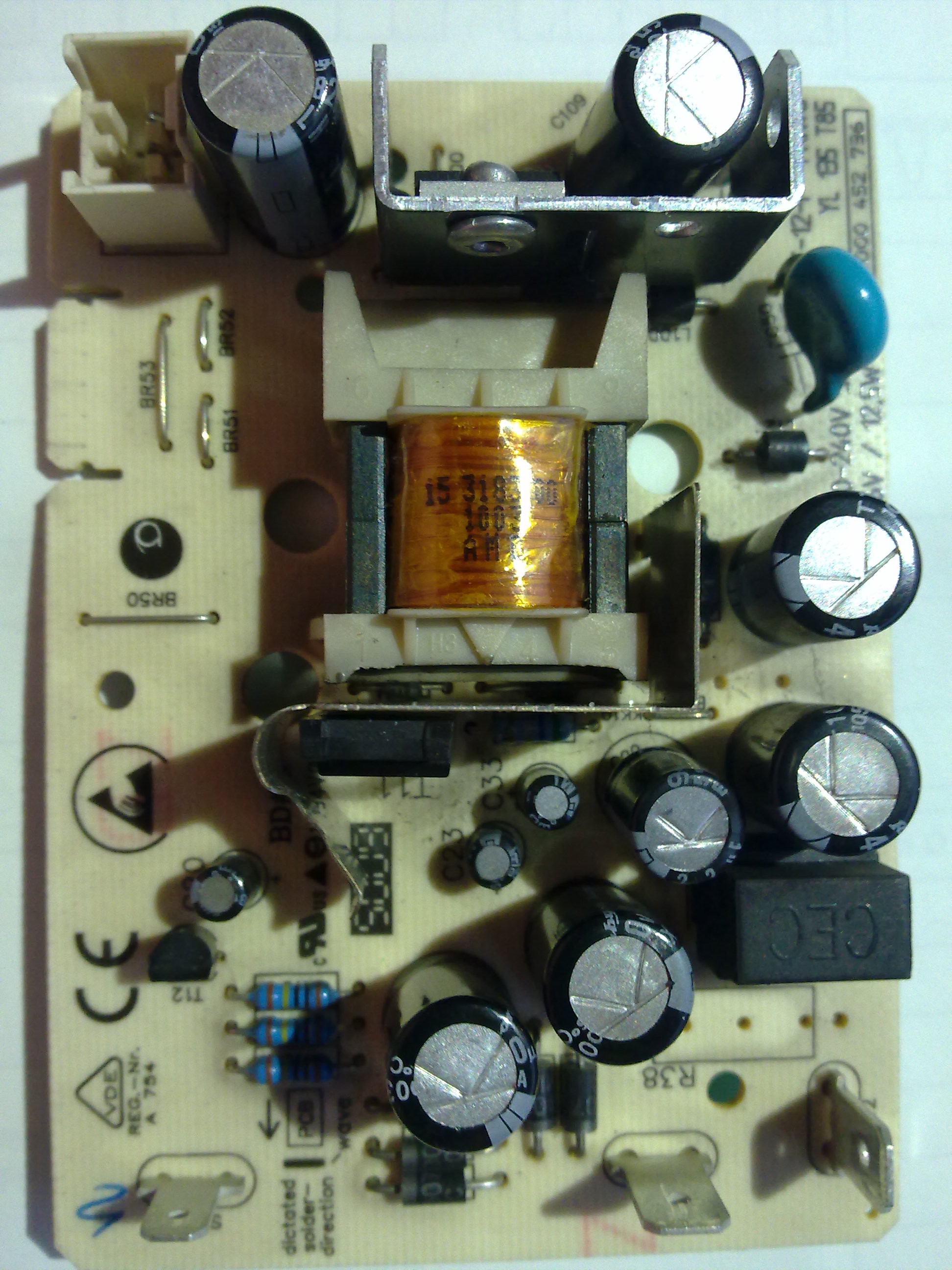
what does not work is the power supply.
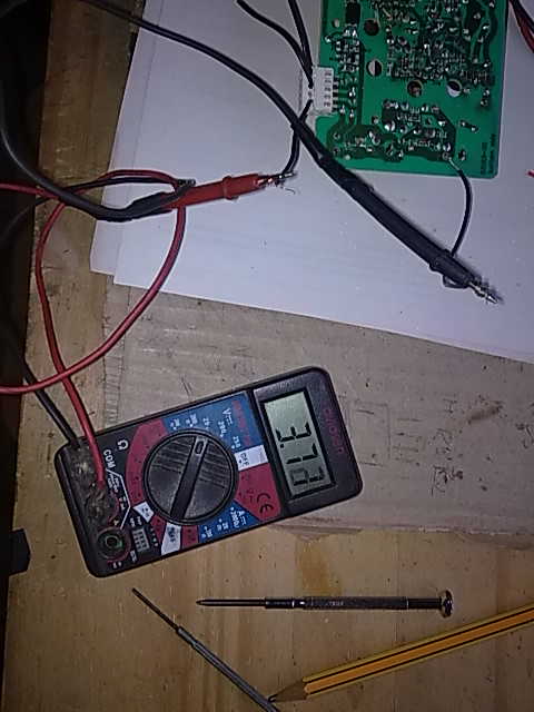
in input there is 220 vac but in output there is not 9.5 vdc.
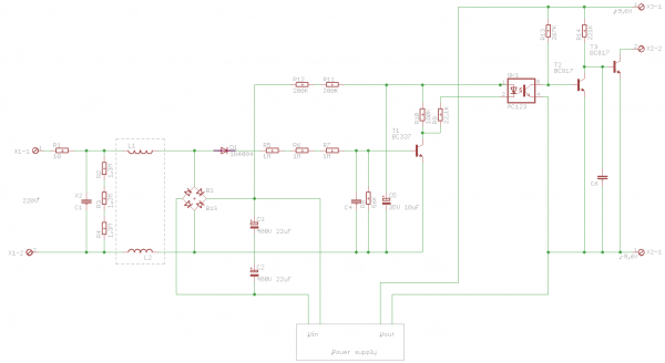
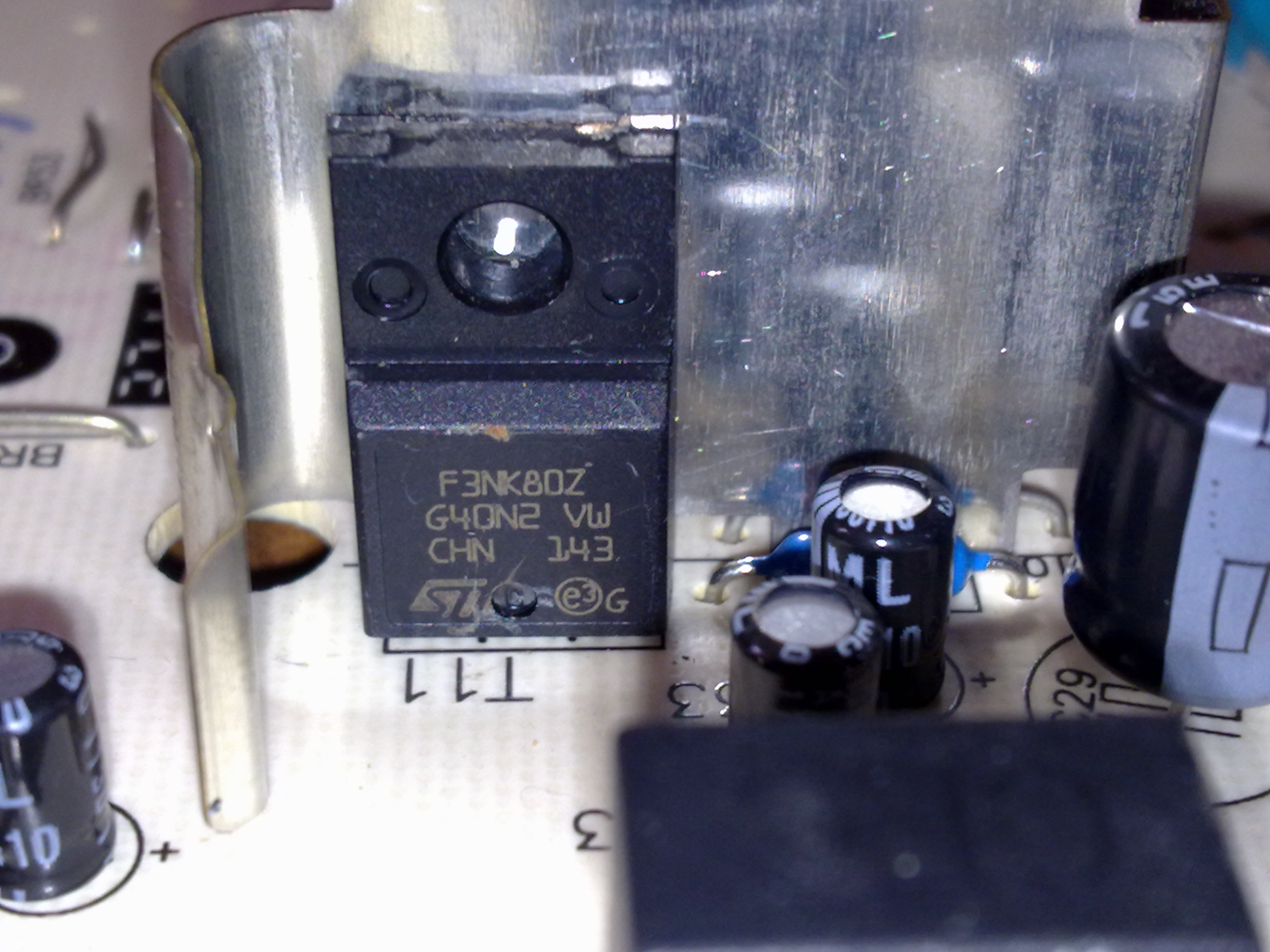
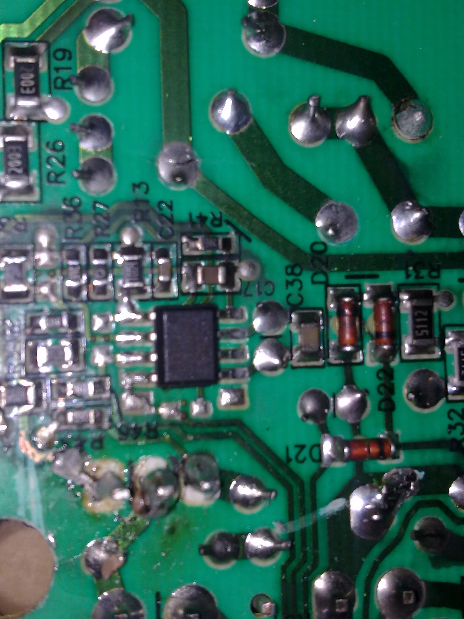
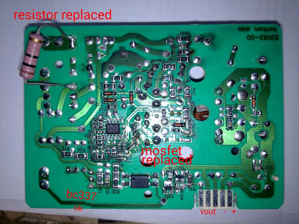
i tryed to replace an resistor from 10 ohm that was broken, but after replacement it is broken again.
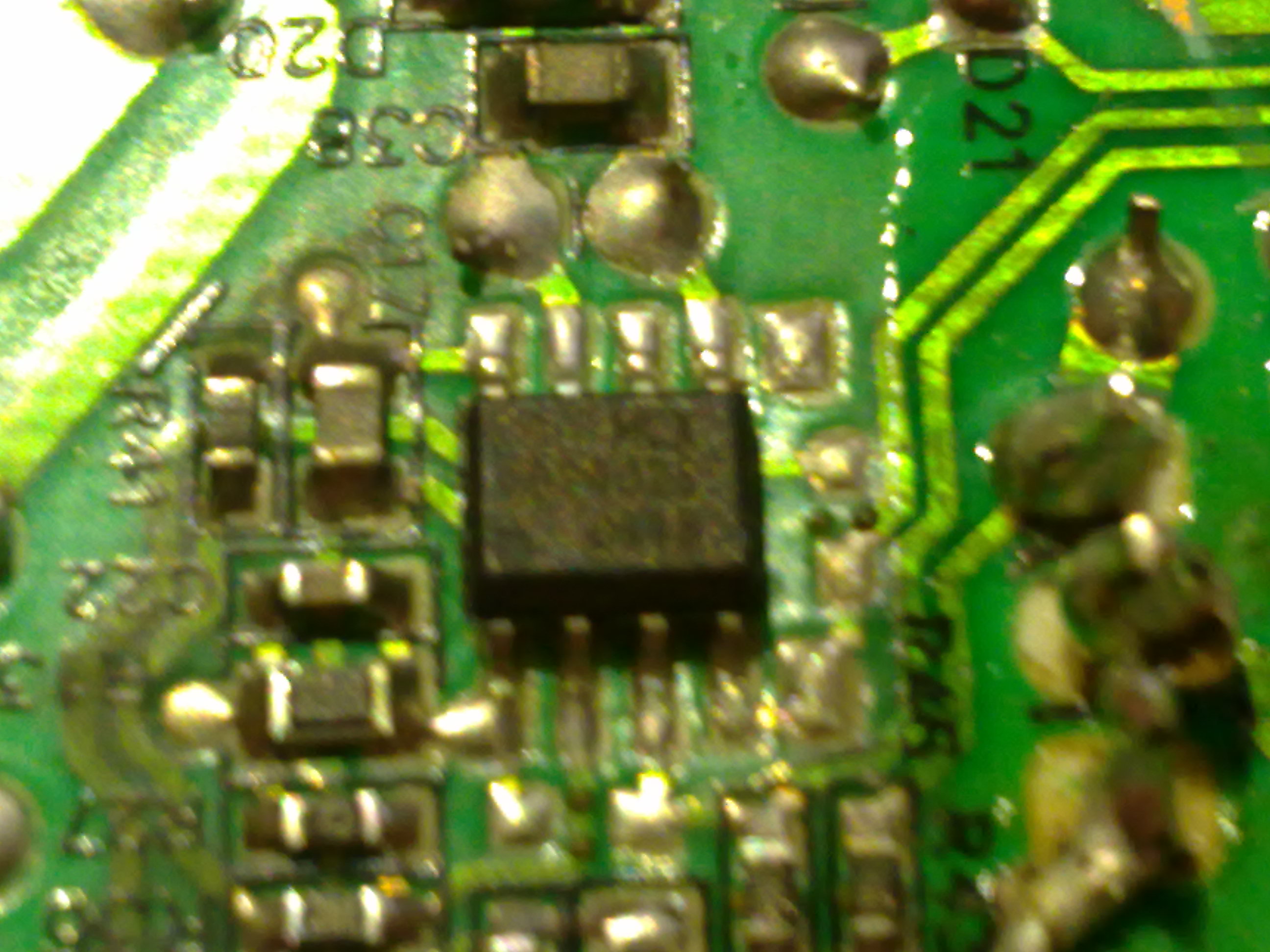
so i replaced the mosfet (F3NK80Z 800 V 3 A 3.8 ohm rds n-channel) with an mosfet n-channel type MTP6N6 (600V 1.2 ohm rds)
now i found the voltage in output but it is 12.5 vdc instead 9.5 vdc.
Can be the rds value of the two mosfet that is different?
else anyone can tell me what is the problem?
good weekend everyone
Regards erchiu
 
Last edited:

these are some photos of the board that not working


regards erchiu
 

Where about in the circuit is the ten ohms? have you got 350+V on the board (rectified AC mains). I would guess that the output voltage is monitored by T101/102 and on the other side of the board is an opto coupler (4 leads on a chip) that controls the pulse width of the oscillator which change the output voltage. Faults could be here.
Frank
 

thank you frank,
you can see the resistor from 10 ohm on third picture (down-right) near the d10 (rectifier bridge).
i mounted it in this point, but before was on the other side in position (R38).
it has one lead connected on the AC line.
i measured the voltage after the rectifier bridge and is 315 vdc.
thank you for your help
regards erchiu
 

Is that measurement with the oven connected? The flat edge connecter has got loads of pins connected to the outside world and one of them could be from the temperature sensing device. No lead, PSU thinks oven is cold and puts maximum volts on it to warm it up and burning out your R10.
Frank
 

ok frank, i understand what that you say, but maybe i have explained badly. If i replace only resistor, it burning soon. Instead, if i replace the mosfet an the resistor, i have an output voltage of 12.5v, but it should be 9.5v. The measurement are with oven not connected. Can be due to the different features of the two mosfet? (they have different rds values). best regards erchiu.
 

can i to solve the problem, mounting an resistor (2 ohm) between trasformer and mosfet?
 

smps power supply not work

hi everyone,
is passed one year to when i posted this thread:

https://www.edaboard.com/threads/314147/
but now still i not solved this problem.

it is an power supply of an oven.


with my work i met a lot of these power supply boards and i would understand its operation.

i replaced the mosfet F3NK80Z in short circuit and the resistor (10 ohm) in input broken.

this module should give 9,6 dc volts in output with 220 AC in input.
after the replacement, i have an output voltage of 4,35 dc volts.

i have another board like this and i did some measurements.
also without load i have an voltage in output of 10,35 volts dc.

on this board the is an IC labled with:

MLX 02402B
0948


i searched on web, but i not found nothing

can you suggest some measurement to do.
thank you
erchiu
 

Re: smps power supply not work

When the mosfet and the gate resistor are blown then the IC or transistor that drives the gate is for sure blown too. You have to replace all of them to start with because there can be more components damaged.
MLX 02402B is likely to be custom made IC with no datasheet.
 

Re: smps power supply not work

The resistor broken is not the gate resistor,but it is on input of the board, on main line.
 

Re: smps power supply not work

The simple SMPS use optocoupler and zener for feedback and the output can vary +/- 10%. With the SMPS that gives 4.35V check that the TO92 transistor is ok.
 

Re: smps power supply not work

There is a pair of resisters still burnt on the board in the photo.

Melexis is a good company for MLX chips but no longer seem to offer this or any SMPS parts on their website.

Normally it goes like this... an unexpected over voltage saturates the coil (at f) which reduces the impedance from 50% to <10% of original , which blows everything in its path. UNless there are cycle to cycle limit checks or the soft start fails to protect when hot.

It would help if you had a photo and a dozen test points with waveforms or Vdc or ac recorded.
 

Re: smps power supply not work

The bc337 to92 is ok.
I removed and checked the transistor out of the board .
Which are the resistors burned ?
when i connect the main power , the output voltage Increase slowly until about 4 volts , no more.


Re: smps power supply not work

I checked in this time, they are from 2.5k and are ok
 

Re: smps power supply not work

what is the part number and curent transfer ratio of your photo-coupler(P781F XXX?)? Have you replaced it?
 

I just successfully repaired a Siemens oven with exactly the same type of power supply. Instead of repairing the schematic with unknown chip I replaced this one with another (Chinese :)) power supply and added the rest of the clock schematic by myself. If anybody is interested in particularities I can describe it here. Should I?
 

If anybody is interested in particularities I can describe it here. Should I?

One they post in a thread, members normally receive notifications (at this forum and via email) when further posts are added. They can return to this thread and read your offer.
 

Anyway... Here the solution I just implemented in my Siemens HB86P575 that has this type of power supply. I found that the power supply is 9.6V 12.5W, but has 5-pol connector. A little bit of reverse-engineering showed that the pins 1 and 5 are connected together to +9.6V, pins 2 and 4 are the minus pol and the pin number 3 is an open collector signal of powerline frequency (50/60 Hz)!

Yes, this modern Siemens device with a color LCD display uses power frequency to drive the clock! Unbelievable, Siemens!

If you just attach a power supply with enough power to the pins 1+5 and 2+4 and leave the pin 3 unconnected, following occur: The oven starts, shows "Siemens" on the display, then shows the clock for maybe 100ms and reboots. So you need this signal to drive the oven.

Here is my solution. I bought a power supply 12V 24W:

8409046900_1442617540.jpg


It was possible to set it to 9,6V using the small trimmer near the connectors. The main problem is to get this powerline clock here. I reverse-engineered the circuit, which makes this clock:


It's just for your inspiration. I found this schematic too complicated for this easy purpose. So I decided to make a simple one additionally to the power supply module. This version is for 230V main supply. The output transistor of the optocoupler is connected with its emitter to -9.6V and collector to the pin 3.

7105769200_1442617666.png


And mounted all on a piece of board. Here how it looks like:

8284869000_1442617742.jpg


The oven started and is still running :)

I hope it helps somebody to repair this oven, the prices for spare parts from Siemens are too high for me.

Disclaimer: Use at your own risk! Powerline voltages are dangerous and so on... :)

--

Maybe it's not a so ideal solution, but it works.

PS. Out of some reasons inserting images to the forum didn't work for me, so I used external image hosting. If some images should disappear, please contact me shortly, I'll reupload them.
 
Last edited by a moderator:
  • Like
Reactions: erchiu

    erchiu

    Points: 2
    Helpful Answer Positive Rating
as I understand, the emitter to the power supply and the collector to 3 wire
 

Status
Not open for further replies.

Part and Inventory Search

Welcome to EDABoard.com

Sponsor

Back
Top