Continue to Site

Welcome to EDAboard.com

Welcome to our site! EDAboard.com is an international Electronics Discussion Forum focused on EDA software, circuits, schematics, books, theory, papers, asic, pld, 8051, DSP, Network, RF, Analog Design, PCB, Service Manuals... and a whole lot more! To participate you need to register. Registration is free. Click here to register now.

Output voltage of opamp is lower when load is less.....doesn't make sense?

Status
Not open for further replies.
T

treez

Guest
Hello,

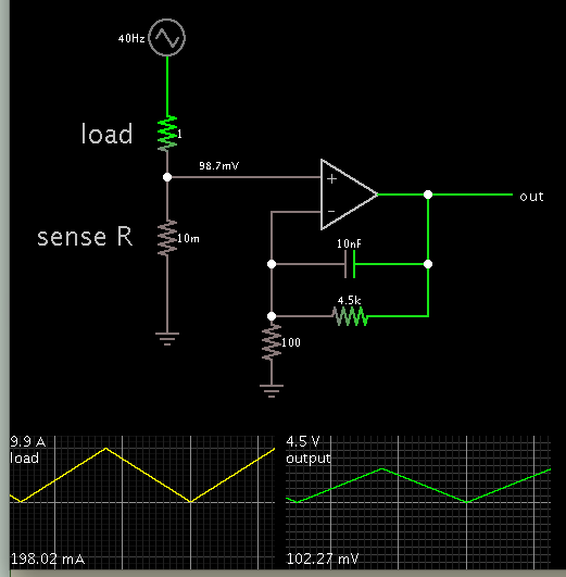
I am using the following differential amplifier to measure current in the sense resistor.

I dont need great accuracy, but just need to know if its 1A, 2A, 3A, ...10A
schematic:
https://i45.tinypic.com/72tvsi.jpg

(the opamp used will be OPA335 .....-> https://www.ti.com/lit/ds/symlink/opa335.pdf )

....when the current is 1A, the output of the opamp will be just 100* 1mV = 100mV.

...unfortunately, page 3 of the OPA335 datasheet says that the VOL of the OPA335 is 100mV.....so does this mean that i wont be able to measure this 1A current?


Also, regarding the VOL value on page 3 of the OPA335 opamp datasheet, i dont understand how VOL is lower when the load is 100K, compared to when its 10K.......i would have thought that the 10K load would make the VOL lower than when there was a 100K load?
 

I don't see any VOL on page 3.

Are you referring to AOL? That is the open loop gain versus the output load versus how close the output is the power rails. It will have negligible effect on your measurement.
 
  • Like
Reactions: treez

    T

    Points: 2
    Helpful Answer Positive Rating
Hi Crutschow...i am referring to "voltage output swing from rail"

...as you know, all op amps, even rail to rail ones, cannot produce output voltages within usually about 100mV of the rails....(at least i think so)?
 

OK, now I understand your question. The voltage is how close to the rail you can go. Thus 10mV with a 100kΩ load is closer to the rail than 100mV with a 10kΩ load. But that would be expected with the load common going to a voltage that is half-way between the rails as the note on the top of the page states. How close you go to the rails is dependent upon how much output current the op amp has to supply. With a load going to the negative rail (ground) you should be able to go essentially to zero volts at the output since the load requires no current at zero volts. If you look at the OUTPUT VOLTAGE SWING vs OUTPUT CURRENT graph on page 4, you will see this.
 
  • Like
Reactions: treez

    T

    Points: 2
    Helpful Answer Positive Rating
The op amp will detect a differential input down to a mV (or less) across your sense resistance.

It will amplify the signal to whatever gain you build into the network.

A sense resistor of .01 ohms carrying 10A will need to dissipate 1 W. You can make this from a 12 inch length of 20 ga copper wire. (The table says it is 98.496 ft/ohm.)

You may not get 5V output. Probably 4.5 max.

To get 4.5V output when 10A is at the load, you should set gain at 45.

Here is a prospective schematic. It's similar to a real circuit I made to detect current flowing from solar panels to a battery bank.


I set the lowest op amp output to be .1V. This corresponds to a load current of 200 mA. I believe you'll be able to read lower than that.

The tricky part will be to adjust it for 0V output when no current is flowing in the sense resistance.
 
  • Like
Reactions: treez

    T

    Points: 2
    Helpful Answer Positive Rating
Status
Not open for further replies.

Similar threads

Part and Inventory Search

Welcome to EDABoard.com

Sponsor

Back
Top