Junus2012
Advanced Member level 5
Dear All
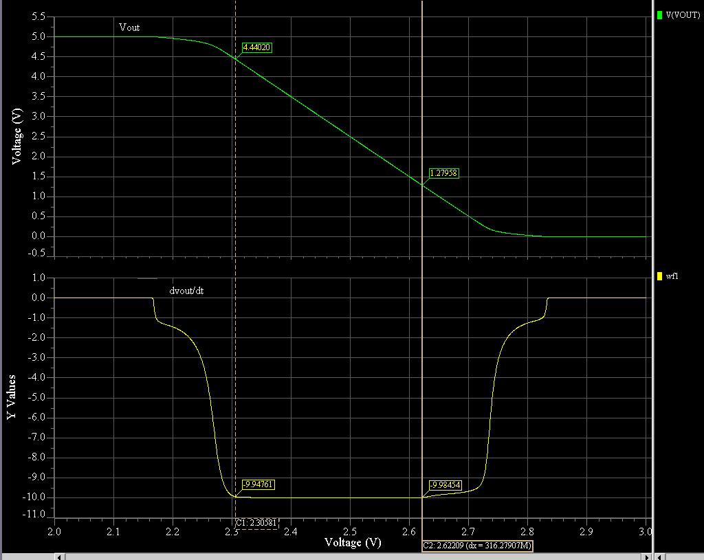
I am simulating the output swing saturation regionof my OTA . I am using cascode load so I was expecting to get limited out swing due to the cascodse but I surprised that I am getting approxiametly rail to rail output saturation range.
The method I am using to simulate the output range is by connecting the OTA as an inverting amplifier with gain 10, the input voltage is in the range if the ICMR so it will affect the output properties.
do you have any reason to explain my case?
Thank you