Continue to Site

Welcome to EDAboard.com

Welcome to our site! EDAboard.com is an international Electronics Discussion Forum focused on EDA software, circuits, schematics, books, theory, papers, asic, pld, 8051, DSP, Network, RF, Analog Design, PCB, Service Manuals... and a whole lot more! To participate you need to register. Registration is free. Click here to register now.

Oscillator Crystal 20Mhz

Status
Not open for further replies.

Linspire

Full Member level 5
Joined
Sep 1, 2011
Messages
303
Helped
1
Reputation
2
Reaction score
1
Trophy points
1,298
Location
M'sia
Activity points
3,279
Hi, I want to ask how to built a circuit which generate square wave of 20MHz using crystal oscillator20MHz which's two pins.
 

By the way, how do I check the clock signal from the oscillator (inside the ucontroller) if I used external crystal oscillator to input to RA7 ?
What I mean is output from any where from the pins.
Linspire
 

I don't know if you can do that when using an external crystal. I know that it can be done when using RC oscillator.
 

By the way, how do I check the clock signal from the oscillator (inside the ucontroller) if I used external crystal oscillator to input to RA7 ?
What I mean is output from any where from the pins.
Which circuit you are referring too?
Upload here to get help.
 

Which circuit you are referring too?
Upload here to get help.
Hi, Raza
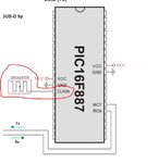
Here's the attachment of overall diagram of PIC16F887.
osc1.JPG

From the circle/highlight CLKIN & CLKOUT,
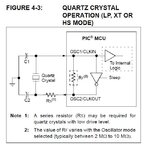
When I put in HS mode for my mikroC project settings, and put two 30/15pF parallel with my RA7 and RA8 and external crystal 20Mhz which shown in PIC16F887's datasheet diagram below.

osc3.JPG

When I used oscilloscope measure, it only can measure the noise not the crystal square wave frequency.
So I'm trying to ask, is there possible get clock signal out to any pin outputs PIC16F887 to make sure that I got correct result of 20Mhz.

osc2.JPG

I'm suspect mikroC user manual example library code, which clock signal (squarewave) set into CLKIN directly (not as using external crystal to generate clock signal).
That's why I may thinking to built circuit can generate 20Mhz square wave from crystal oscillator.

Regards
Linspire
 

You can buy ready built clock units pretty cheap, that just take power and give a squarewave,
I have had no problems with crystals recently (everything I've tried has worked!) but I did find that 2 chips wouldn't work above 4Mhz, so I'll say try a chip-swap 1st just in case, worth a try eh, :)
NEAL

---------- Post added at 13:39 ---------- Previous post was at 13:36 ----------

can you post a shot of the "Noise" you are measuring on the scope? Is there any pattern to it changing the trigger point?
Neal

Hi,
What'd you mean built clock units ?
Any links for show the product ? Or can you go these website which valid for my country :Cytron Technologies - Your Online Store for robotic parts, embedded system, electronic components and hobby kit ; **broken link removed**

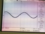
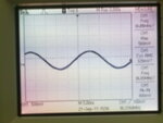
Here's the noise I measure with voltage around 20mV with good "sine wave" waveform.
210920112330.jpg
210920112329.jpg

Regards,
Linspire
 
is the noise 36.2 (read off scope) Mhz?? :)

Frequency Control |Buy Frequency Control online | RS Components
This is what I mean, sorry I a bit pushed so this is UK site... 4pins, +, gnd , gnd and ~!!! :-D
NEAL

---------- Post added at 14:26 ---------- Previous post was at 14:25 ----------

Sorry, they are £100 each!!!! Cor, thats 75litres of Petrol...!!
Appologies, I expected them to be <£10
NEAL

---------- Post added at 14:30 ---------- Previous post was at 14:26 ----------

at 20mv I think you're right in thinking its noise... I presu,e this is the clock2 pin?
NEAL

---------- Post added at 14:31 ---------- Previous post was at 14:30 ----------

there is the OSCCON register to look at in code, if you're altering this directly it can set internal or external clock or crystals... Are you OK setting the config bits to make the chip use XT oscilator options?
NEAL

Wow, that's too costly for me as student.
The noise I mention is I directly measure from CLKIN and CLKOUT there, after/without put capacitor parallel with those pin, the noise frequency reduced from 100Mhz to 36Mhz, which doesnt really measure oscillator frequency.


Regards
Linspire

---------- Post added at 21:37 ---------- Previous post was at 21:34 ----------

I have tried tweak the OSCCON setting, the maximum clock speed I can get from CLKout is 2Mhz due to Fosc/4.
8Mhz/4=2Mhz.

Regards
Linspire
 

yeah, 2Mhz,you'll only get 8Mhz from internal clock... in OSCCON the last 3 bits set wether its internal clock, external clock, or crystal, you checked all 3 combinations?

I know what you mean about the cost of those buddy! I Didnt' realise they were that much, if you manage to make one (a 20Mhz crystal ocscilator) you know how much you can sell them for now!!! :p
NEAL

---------- Post added at 14:43 ---------- Previous post was at 14:42 ----------

[and put two 30/15pF parallel with ]
? why put two in parralell? (4 total)

Have you tried just one 15pf on each side?
NEAL
 

Sorry, I mean each capacitor parallel (total of 2 ).
My 16F887 datasheet OSCCON 's last 3 bits set for Status Bit of High Frequency and Low Frequency and System Clock.

Any idea how to built 20Mhz square wave circuit from crystal oscillator 20Mhz ?

Regards
Linspire
 

Measure the clock at clkout and GND not across clkin and clkout
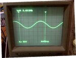
Hi, today I did try measure in CLKOUT only and leave out negative/gnd probe and measure around 3V with 20Mhz.
However, when I connect the oscilloscope negative/grd probe to ground, I got zero or may be noise signal.

Regards
Linspire
 

[yeah sorry, was looking at 88 by accident!]
so you OK with setting the clock source in the config word? Should be set to HS mode....

"Gnd" to osc2 will kill everything if GND's are common (through earth or anything) so GND should goto GND, you know that I recon mate,
NEAL
 

MikroC project setting allow me to set to HS** mode.
Yap, GND probe should go GND, any idea how to explain why I just connect positive probe to CLKOUT and negative proble without connecting, it shows 3V with 20MHz ?
Whereby, when I connect to negative probe to GND, it directly shows GND.

Regards,
Linspire
 

Hmm, I not sure about the GND thing, but I know the feeling!!! It seems happen often in real life!! Are you sure your power suppliy isn't tied to earth in some way? Can you isolate the circuitboard, dunno, run it on a battery for 10 mins just to see...

Regards
NEAL

---------- Post added at 15:36 ---------- Previous post was at 15:35 ----------

If you've set HS mode dont go near the OSCCON register either
 

Yap.
Anyway, back to my thread, built 20Mhz square wave as clock signal fed into PIC16F887 using oscillator crystal.
I'll try built this circuit as suggested by Tahmid.

Hi,
Try something like this: COLPITTS 1 To 20 MHz Crystal Oscillator

Hope this helps.
Tahmid.

Anyone suggest better solution ?

Regards
Linspire
 

Hi linspire,
I don't know whats the problem with your scope or measuring procedure. Here is an attached image from one of UPS designed boards. Am using PIC16F84 and operating at 3.579 MHz. You can see the scope has measured it as 3.603 MHz, as the cursors may not been exactly placed.ScopeIMG.jpg
Your uploaded image is blur, I can not read the screen. It must read 20MHz in your case.
Any further help is welcomed.
 

I think you're on the right lines... If a "Built Oscilator Module" costs £100, you could dedicate a whole PIC and Crystal just to the job and would work out far more enonmical, AND, if you can get a Sine-wave you're only a (comparator) step away from a squarewave, and isn't there a comparator built into the 16f887?
Best regards
NEAL

---------- Post added at 16:56 ---------- Previous post was at 16:54 ----------

if I used external crystal oscillator to input to RA7 ?
this suggests a "PRE-BUILT osciliator module"... We're looking at a crystal resonator isn't it?
NEAL
 

Status
Not open for further replies.

Similar threads

Part and Inventory Search

Welcome to EDABoard.com

Sponsor

Back
Top