Continue to Site

Welcome to EDAboard.com

Welcome to our site! EDAboard.com is an international Electronics Discussion Forum focused on EDA software, circuits, schematics, books, theory, papers, asic, pld, 8051, DSP, Network, RF, Analog Design, PCB, Service Manuals... and a whole lot more! To participate you need to register. Registration is free. Click here to register now.

[SOLVED] Oscillator connection to microcontrollers

Status
Not open for further replies.

mrinalmani

Advanced Member level 1
Joined
Oct 7, 2011
Messages
463
Helped
60
Reputation
121
Reaction score
58
Trophy points
1,318
Location
Delhi, India
Activity points
5,285
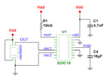
I have a four terminal crystal oscillator. The four pins are: Vdd, GND, Enable, OUT
The frequency output is wrt Ground.

Microcontrollers have two terminals for oscillator input, and the oscillator is supposed to be connected in a floating manner across the two pins.
However, since my crystal-oscillator output is wrt ground, is it ok to connect one oscillator-input-pin of the MCU to the ground, and the other to the output of the crystal oscillator?
Thanks!
 

Hi,

Its all down to the correct description, refer to the Oscillator section of the chips datasheet.

You use the OSC1 and OSC2 pins when you want to connect a crystal to the Pic and use the Pics internal circuitry to act as the oscillator; you also must select the correct OSC parameter of the Config statement eg XT or HS.

For your four terminal Oscillator, which means it has its own inbuilt crystal and oscillator circuitry, then you only need feed its output into OSC1 pin and change the Config to EXT OSC.
 
Thanks for the reply, but I cannot configure anything, my MCU is not waking up.
 

Hi,

Check the difference between a (passive, 2 connections) xtal and an (active, 4 connetions) oscillator.

Your four pin device is an oscillator. You have to supply it with VCC and GND and "enable" it.
Connect it´s output to the uControllers input. The description you will find in the controller´s datasheet.

Look into the controller´s datasheet on how to setup for external oscillator connection.


Klaus.
 

Check the voltages between oscillator pin and ground.

If The Oscillator pin voltage is near by Vdd/2 is oscillator is working good.

Post your oscillator and controller details.
 

Hi,
Check the voltages between oscillator pin and ground.

If The Oscillator pin voltage is near by Vdd/2 is oscillator is working good.

This testing sometimes works but sometimes does not.
An xtal oscillator is something sensible. On some circuits the capacity (impedance) of voltmeter probes or scope probes make the oscillator stop working.

Klaus
 

All CMOS oscillators use an inverting gate or a simple inverter for negative feedback to make an Xtal oscillator with 2 caps and an internal 1M feedback resistor for self-bias.

When using an external clock for most including PIC's, the designation is OSC1 for input and OSC2 for output.

Thus you only need to connect directly to OSC1 (& gnd).

image.jpg


This is same as what wp100 said.

Both clock and MCU must be powered from the same source.
 

Hi,


This testing sometimes works but sometimes does not.
An xtal oscillator is something sensible. On some circuits the capacity (impedance) of voltmeter probes or scope probes make the oscillator stop working.

Klaus

I did this many of times. Even all times I get better results.

And also measurement equipment matched with better impedance circuits.
 

Thanks for the help everyone!
I think post #2 (wp100) should have been an end to the thread.
Post #7 (SunnySkyguy) makes it further clear.
I've got the answer, but I am anyway attaching a photo of my old schematic. In the new one that I will make, I will simply leave OSC2 pin floating.
Please point out errors, if still present.
Thanks!
 

Attachments

  • Capture24.PNG
    Capture24.PNG
    27.7 KB · Views: 74

Hi,

We still don't know what ucontroller and what oscillator and what voltage you use. Without these informations we cannot give you optimal assistance.

The schematic is ok so far, as long as you leave OSC2 open.
Check if the oscillator needs H or L to enable it.

Because the oscillator is an active circuit you could spend an extra 100n capacitor at it's supply.

Klaus
 

I am using dsPIC33FJ06GS001
Vdd = 3.3V

I appears that this particular model is not supported by pickit-2 (although pickit-2 shows support for dsPICs)
 

The informations missing in this discussion can be found in a parallel thread https://www.edaboard.com/threads/321962/

One more example that shows why related posts should be kept in a single thread, even if you feel that the new post isn't exactly fitting the title of the first started thread. But it often turns out that both posts are actually discussing the same problem.

As in this case: A dsPIC isn't working (no programmer access). First idea, is it a problem of the clock oscillator connection. Second idea, programmer interface problem.
 
Hi,

I just had a view on dspic datasheet. There are a lot of clock options. A careful reading of datasheet isnecessary...

Is your controller running now?

If not, please tell us what setup you like, and what you tried so far. Also your oscillator type and frequency.

Klaus
 

Status
Not open for further replies.

Similar threads

Part and Inventory Search

Welcome to EDABoard.com

Sponsor

Back
Top