mrinalmani
Advanced Member level 1
- Joined
- Oct 7, 2011
- Messages
- 463
- Helped
- 60
- Reputation
- 121
- Reaction score
- 58
- Trophy points
- 1,318
- Location
- Delhi, India
- Activity points
- 5,285
Hi!
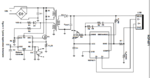
Most flyback controller ICs have a feed-back pin that needs to be connected to the output of an opto coupler. What is the mechanism behind this?
I mean what is required by the IC at the feedback pin? Some sort of voltage? current? I understand that it needs an optocoupler, but what is the optocoupler doing?
I have tried to find the working behind this but I can only find example circuits.
My real purpose is to use this IC NCP4371 which is a "quick charge 3.0" controller IC for flyback topology. But I need to use it in buck topology, not flyback. I cannot find any controller IC for quick charge 3.0 that is made for buck topology.
I want to tweak this IC for buck operation. An on board MCU will control the buck controller.
Please help...
Thanks