Continue to Site

Welcome to EDAboard.com

Welcome to our site! EDAboard.com is an international Electronics Discussion Forum focused on EDA software, circuits, schematics, books, theory, papers, asic, pld, 8051, DSP, Network, RF, Analog Design, PCB, Service Manuals... and a whole lot more! To participate you need to register. Registration is free. Click here to register now.

Opto-Coupler and TIP142

Status
Not open for further replies.

assadmahmood

Junior Member level 3
Joined
Oct 23, 2011
Messages
30
Helped
0
Reputation
0
Reaction score
0
Trophy points
1,286
Location
Karachi Pakistan
Visit site
Activity points
1,531
Greetings EveryBody!
I am driving high current transistor (TIP142)by mircocontroller and load is getting 6Amp at 28VDC,

Circuit:
I am directly interfacing base of TIP142 with microcontroller pin with 1KΩ resistor in between.

Problem:
After some time as I turned the circuit ON, microcontroller starts getting restart again and again.
I have option to use opto-coupler between then but I want to know the reason thay why this is all happening and why we need isolation??
 

it will be helpful if you provide more information like how you power the circuit and load plus how you hold your reset pin? It will be helpful if you attach schematic.
 

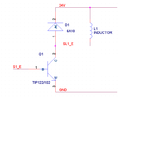
Here is the schematic and my load is a solenoid which is being operated on 5.9Amp, 28VDC, In schematic TIP122 and 6A10 diode are being used but later on I replace them with TIP142 and 10A10 (10Amp diode).

Extremely sorry for late replying. TIP_n_solenoid.PNG
 

Ok I would try that and will let you know about the update.

But can you tell me that why do we need isolation by using optocoupler between microcontroller and high current drivers (TIP or high current transistors)?? is there any possibility of reverse current from the driver's base??
 

Your supply voltage is 28V, So isolated gate drive not required.
You can drive the transistor through a resistor and a diode.(see the result)
Microcontroller was reset because of differential mode noise generated due to solenoid.
You have to use PI filter on the 28V entry.
Use one 0.1uf ceramic capacitor very close to microcontroller VCC pin

What about switching characteristic, Continues or pulse?
If it is pulse, you have to suppress the back emf of solenoid , Back emf is directly proportional to the inductance and current of the solenoid.
 

Just on a slightly different tack , you haven't got the watchdog resetting the processor by any chance.
It can happen that you get sidetracked and end up looking for faults in the wrong place altogether!!
There are a few things that can cause a processor reset , a watchdog timeout being one of them.
A brownout reset (power supply to processor dipping to low) is another possibility.
 

I am giving 500ms pulse on it after every 30 seconds but just after 5 or 6 iterations TIP gets heating up very much. Watchdog timer is disabled, not using that. Coil resistance is 4.9 ohms.

Resetting issue is solved and many thanks for you guys for your so kind support.
 
Last edited:

Vce sat for your TIP142 is about 2V I think. That is about 12W dissipation. Even for low duty cycles , it's going to get warm.
I'd replace the TIP with an n channel FET. Something like an IRF1010E. There are many great fet's around that will do the job
with almost no dissipation. With such a low duty cycle and switching frequency , gate charge is not really an issue and you can get 1mohm
fets no problem. Power dissipation would only be 36mW.
 

But Sir the issue is I have to switch off transistor rapidly but I heard that FETs or MOSFETs dont switch off if you have to switch them off suddenly or rapidly
 

You have not said how fast is rapidly.
1S , 1ms , 1us , 1nS , 1pS?
With simple circuitry a few 10's of nS is a usual switching time. Will depend on gate charge.
 

1ms But not more than that, and does it require any driver
(opto coupler/2N2222A/BC547 etc) to operate if it has to be driven by a microcontroller or any IC (for example 74HC595 shift register) ???
 

1mS , easy.
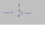
You can get logic level mosfets that can be driven directly from the micro/logic gate.
If you want you can also use a 1transistor(inverting) or 2 transistor (non inverting) level shifting cct.
Do you have a copy of LTSpice. Very easy sort of stuff to simulate.

This mosfet would do , but there are hundreds that will work for your application.
https://www.onsemi.com/PowerSolutions/product.do?id=NTD5806N
 

How is this going to help.


ROTFLMAO
haa haaa haaa

- - - Updated - - -

Seriously though , Ogu Reginald means this:
 

Attachments

  • images.jpg
    images.jpg
    8.8 KB · Views: 71
  • totempole output.jpg
    totempole output.jpg
    55.4 KB · Views: 94

Status
Not open for further replies.

Similar threads

Part and Inventory Search

Welcome to EDABoard.com

Sponsor

Back
Top