Continue to Site

Welcome to EDAboard.com

Welcome to our site! EDAboard.com is an international Electronics Discussion Forum focused on EDA software, circuits, schematics, books, theory, papers, asic, pld, 8051, DSP, Network, RF, Analog Design, PCB, Service Manuals... and a whole lot more! To participate you need to register. Registration is free. Click here to register now.

[SOLVED] optimized band-pass filter design

Status
Not open for further replies.

Md. Sarwar Jahan Sabuj

Newbie level 4
Joined
Mar 6, 2012
Messages
6
Helped
0
Reputation
0
Reaction score
0
Trophy points
1,281
Activity points
1,336
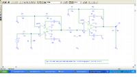
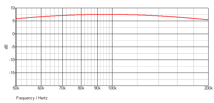
I want to create an optimized band-pass filter using two op-amp uA741. My required band is 85-115KHz with carrier frequency 100kHz. This design will be a part of Frequency division demultiplexer. It's very necessary to optimize the design for recovering an original message signal. In schematic (using orcad pspice 9.2) i have found better result but i think this is not optimzed. Pls help me in this regard. My band pass design has been shown in picture. N.B. i want only to pass the required band.
 

Dear Md. Sarwar Jahan Sabuj
Hi
I don't think a 741 is good for your aim , try better op amps (e.g TL series )
Best Wishes
Goldsmith
 

What are the optimization objectives?

This is a simple first order filter, in so far uA741 can still work for it. Two restriction should be observed:
- uA741 can't drive a filter with around 150 ohm impedance. The low-pass RC circuit must be dimensioned with at least factor 10 higher impedance
- limited uA 741 slew rate will seriously restrict the power bandwidth of the circuit (undistorted signal < 1 V)
 

Dear FvM
Hi
I don't think that 741 can handle this project , because of these problems :
1- low GBWP
2- low slew rate .
Isn't it ?
why not better opamps ?
Best Regards
Goldsmith
 
Last edited:
I agree that a 741 is, at best, marginal for use in your task.

Since you are using op amps, why not configure them to at least a 2nd order function to give a faster rolloff characteristics at the band edges? You can use the free FilterPro software from TI to simplify the design process.
 
I agree that a 741 is, at best, marginal for use in your task.

Since you are using op amps, why not configure them to at least a 2nd order function to give a faster rolloff characteristics at the band edges? You can use the free FilterPro software from TI to simplify the design process.

Dear Crutschow,
Hi,
You have suggested to use filtrepro software. So i have used "Filter Wiz PRO v5" software. But i am in a little bit problem. I am not properly using this software for lack of documents. If u have have any document or manual to operate this, please give or at least inform me about the related resource.

Best regards
Sarwar

---------- Post added at 12:06 ---------- Previous post was at 12:02 ----------

Dear goldsmith,
If I use LM324 can I solve above problem?

Best regards
Sarwar
 

Dear Crutschow,
Hi,
You have suggested to use filtrepro software. So i have used "Filter Wiz PRO v5" software. But i am in a little bit problem. I am not properly using this software for lack of documents. If u have have any document or manual to operate this, please give or at least inform me about the related resource.
................
I'm not familiar with Filter Wiz PRO v5 software so can't help you there. But FilterPro is easy to download and use so if you download that I should be able to answer any questions about its use.
 

Hi Sarwar

If you use two bandpass filters tuned to slightly different frequencies, you can get a nice response like in the picture below.

The peaks on each side are a good idea. From your description, it sounds like the 100KHz signal is modulated with an audio signal limited to 15KHz bandwidth. After that is demodulated, you can pass the audio through a low pass filter with -3dB at 15KHz. That will compensate for the peaks in this filter and give a flat frequency response overall.

uA741 is too slow.
LM324 is also too slow.
TL072 has high enough slew rate, but it's GBW is still quite low.
NE5532 should be OK. It has good slew rate and GBW.
Other opamps may be better, but probably more expensive.

Depending what opamp you use, you may have to change the resistor values a little.

Regards - Godfrey


filter resp2.GIF
 
Last edited:
Dear godfreyl
Hi
Of course it is not correct ! that you use some filter with identical values as a chain ! you should use a buffer between those filters . BTW : as i can see at your simulated result , the cut off frequency changed , a 2nd order filter means , that your cut off frequency is constant but , at cut off frequency , you increased unbrace ratio . ( 6dB ) but your result , hasn't meaning of proper 2nd order filter .
Best Regards
Goldsmith
 

The original post isn't clear about a design restriction to a particular filter order or a simple first order HP/LP cascade in particular. Unfortunately, it also misses any specification except for a pass band.

godfreyl mentions correctly, that optimizing the filter characteristic can also mean to use a different filter topology. The suggested fourth order filter (about 3dB p.b. ripple Chebyshev) is a good example for a filter with better stop band attenuation.

goldsmith, I don't exactly understand to which problem you are referring in your post. The suggested filter isn't said to be a 2nd order one
 

Dear FvM
Hi
I'm referring to the result of simulation ( two responses )

At his design , the cut off frequency changed . ( red shape instead of blue shape ) .
And i don't think it is correct to use some filter with identical value of components , in series together . i think , the values should change or , add a buffer between those two stages .
Isn't it ?
Best Regards
Goldsmith
 

The filter suggested by godfreyl is cascading two second order band pass filters with slightly different center frequency, the two curves show the individual frequency responses. That's the usual method to build a higher order filter with steep stop band transition.

Both filters are decoupled by the low OP output impedance, you don't need a buffer between the stages. In case of cascaded passive (LC) filters, the coupling is accepted as a fact and considered in the calculation.
 
oops , sorry , yes , you're quite right , i didn't saw the value of elements , carefully , and i thought , those are the same .
Sorry again , and thanks for your clarification .
Regards
Goldsmith
 

I'm not familiar with Filter Wiz PRO v5 software so can't help you there. But FilterPro is easy to download and use so if you download that I should be able to answer any questions about its use.
Dear Crutscow,
Hi,
If u have any necessary document or manual of FiltrePRO, pls submit here.

---------- Post added at 22:28 ---------- Previous post was at 22:17 ----------

Hi Sarwar

If you use two bandpass filters tuned to slightly different frequencies, you can get a nice response like in the picture below.

The peaks on each side are a good idea. From your description, it sounds like the 100KHz signal is modulated with an audio signal limited to 15KHz bandwidth. After that is demodulated, you can pass the audio through a low pass filter with -3dB at 15KHz. That will compensate for the peaks in this filter and give a flat frequency response overall.

uA741 is too slow.
LM324 is also too slow.
TL072 has high enough slew rate, but it's GBW is still quite low.
NE5532 should be OK. It has good slew rate and GBW.
Other opamps may be better, but probably more expensive.

Depending what opamp you use, you may have to change the resistor values a little.

Regards - Godfrey


View attachment 72938

Dear godfreyl,
Hi,
If I use your bandpass design shown above, will it be better design?

Best regards
sjs
 

Best low sensitivity high Q BPF is Salen & Keys design. Here is an integrated solution you can copy.
**broken link removed** What you have is a LPF and a HPF , each is a 1st order filter, cascaded becomes a 2nd order..

A tuned 2nd order is better. and higher order permit wider bandwidth with choices of steep skirts, minimum ripple in passband, minimal phase shift, raised cosine.. etc.. each with names like Bessel, Elliptical, Chebyshev, etc filter design etc. but simple S&K BPF is very low sensitivity to component tolerances. ( as I see sjs as suggested) This has been used for decades with many easy formula for design.

I remember in my grad thesis using a filter I designed based on this but had variable F and variable Q with constant gain. I used to detect whistle tones for pitch controlled sequencer for handicaps. with hose near mouth to mic and user could dial phone or control switches with simple whistle notes
 
Last edited:
Best low sensitivity high Q BPF is Salen & Keys design. Here is an integrated solution you can copy....
Thanks
That looks like a good solution too. It also cascades two second order band pass filters, like what I proposed. Maybe it is less sensitive to component tolerance. I don't know.

---------- Post added at 20:39 ---------- Previous post was at 19:54 ----------

Dear godfreyl,
Hi,
If I use your bandpass design shown above, will it be better design?

Best regards
sjs
Hi sjs

What do you think? The picture below shows the response you will get with the kind of filter Sarwar showed in the first post of this thread.

If you have circuit simulation software, you can check these things yourself. I use the free version of SIMetrix Simplis. It is very easy to use.

Regards - Godfrey


I think the FilterPro must assume that the Designer is aware of the assumptions made for Active Filters using non-ideal Op Amps.

In general I would expect the BW of the device may need to 10x greater than operating range to reduce calc. errors. (depends on tolerance allowed)
Also the power Bandwidth must be 10x greater if large signals are desired on output with low distortion.
Other than that, it is easy to use and read the fine print. Test to verify tolerances.
 

Status
Not open for further replies.

Similar threads

Part and Inventory Search

Welcome to EDABoard.com

Sponsor

Back
Top