Gimlix
Member level 1
Hi everybody!
I am designing an embedded system and I have some doubts with my power supply stage. The system is intendeed for industrial use and it will be powered always by batteries (it will be compatible with systems of 9V up to 90V)
As I am not going to design a whole SMPS for the main stage, I will use a Traco DC-DC converter. The converter IC1 is this one:
**broken link removed**
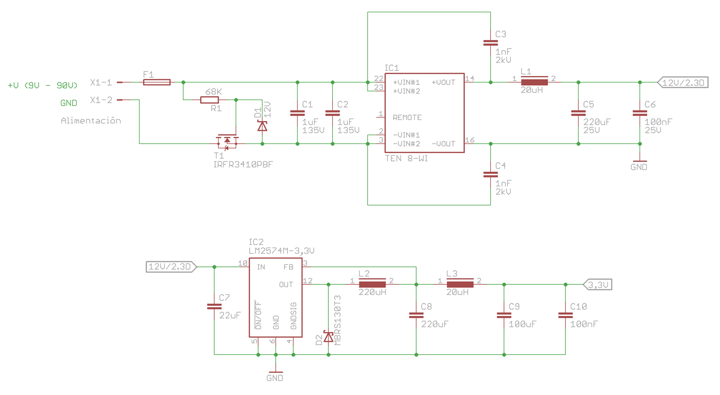
And the schematic I've made is this one:
Regarding this app. note I have some doubts. It says on sheet 49, C1+C2+C3+C4 need to be added for Class A compliance. I don't see the point for adding two 1uF capacitors in parallel, could I just use one capacitor instead of two?
On sheet 51 the app. note says an LC filter is recommended at the input, but I don't know if it should be before or after C1+C2. Any idea? What happens if I don't install this LC filter?
And at the output, as I want to have a clean 12V line, would it be right to add the L1+C5+C6 stage?
The second part of the circuit is a small SMPS build as stated in the datasheet from TI for the LM2574. Do you think the 3,3V output is enough filtered in order to power up a couple of processors and ADCs without big problems?
Any ideas, comments or advices would be awesome. Thanks!
I am designing an embedded system and I have some doubts with my power supply stage. The system is intendeed for industrial use and it will be powered always by batteries (it will be compatible with systems of 9V up to 90V)
As I am not going to design a whole SMPS for the main stage, I will use a Traco DC-DC converter. The converter IC1 is this one:
**broken link removed**
And the schematic I've made is this one:
Regarding this app. note I have some doubts. It says on sheet 49, C1+C2+C3+C4 need to be added for Class A compliance. I don't see the point for adding two 1uF capacitors in parallel, could I just use one capacitor instead of two?
On sheet 51 the app. note says an LC filter is recommended at the input, but I don't know if it should be before or after C1+C2. Any idea? What happens if I don't install this LC filter?
And at the output, as I want to have a clean 12V line, would it be right to add the L1+C5+C6 stage?
The second part of the circuit is a small SMPS build as stated in the datasheet from TI for the LM2574. Do you think the 3,3V output is enough filtered in order to power up a couple of processors and ADCs without big problems?
Any ideas, comments or advices would be awesome. Thanks!