Vermes
Advanced Member level 4
Let's start by defining what is an open loop in system steering (on the other hand I'll show You a closed loop for comparison). Below You can see a basic system example:
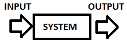
This is an open loop system because it depends only on the input. For example, let us say that we have a washing machine where you set the time of washing. It is washing your clothes for a set of time but it doesn't check if they are clean after that. Some other examples will be shown after the closed loop definition. Now please take a look at a closed loop:
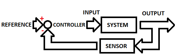
As you can see, we have here a sensor which let us say checks whether the clothes are clean and continues to wash them. Formally we have a sensor which reads the output value of the system and subtracts if from the reference value. This value (the difference between the reference and the sensor value) is called an Error. The controller changes this value to a system input value in order to make it useful (to make it work).
What is a transfer function?
The transfer function is a Laplace Transform of the impulse response of the linear and time invariant system when the system conditions are set to 0.
Imagine a remotely controlled device, let it be a car for example, and let us focus on turning it left and right. In your hands, you have a steering device with a steering wheel to turn it left and right. Important thing now, if you can see the car and react to the angle of steering wheel, this is a closed loop (because your eyes are the sensor) but if you can't see it (it's dark, the car is very far away, it's in another room etc.) it is an open loop. Let's define the blocks for a open loop:
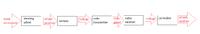
As you can see, there are many blocks (black bocks) that make some operations. Therefore, it's not easy to get the right wheels position depending on the position of the steering wheel. To make it easier, we need to define transfer functions of each block and combine them.
Let's go back to the topic - the open loop transfer function. On the beginning I must say that on a open loop we should also add a controller to rewrite the input value:
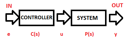
Because we need something which will make the input signal useful for our system. You can understand it, for example, as the wheels controller. Depending on the hand movement (position of the wheel controller), voltage is generated to use it in another black box. The above controller is a mathematical operation which will make the values useful.
Ok. Let's go to some mathematical background how to obtain the transfer function.
As it was written before, the transfer function is a Laplace Transform response to the signal. But what does the Laplace Transform do? The easiest explanation is that it transfers the time domain to the s domain.
Laplace transform:
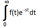
As you can see, this isn't trivial, but you can find many tables with counted values, some of the important values are listed below:
Ok. And back to a basic open loop transfer function example:
For explanation:
u(t) is the arbitrary input
g(t) is the impulse response
y(t) of curse is the output
If you take the Laplace transform of this system:
u(t) goes to u(s)
g(t) goes to G(s)
y(t) goes to Y(s) = u(s)G(s)
where G(s) is the transfer function
Ok. Let's go to an example to make it all easy:
This is a simple harmonic oscillator with mass 'm' and spring constant 'k'. It is subjected to an input forcing function u(t). The motion of this kind of system is:
ma(t) + kx(t) = u(t)
where a is the acceleration.
To find the system response we set u(t) to be equal the signal
u(t) = δ(t)
To solve this equation we need to use the Laplace transform, therefore let's do it using the above table:
ma(t) + kx(t) = δ(t)
m(s2X(s) – sx(0) – x'(0)) + kX(s)=1
we must remember that we don't have initial conditions therefore we have now:
ms2X(s) + kX(s) = 1
X(s)(ms2+ks) = 1
X(s) = 1/(ms2 + ks)
We have now the response function – and as it is called, the transfer function.
If you would need to go to the time domain you would need to get the inverse Laplace function for X(s). You need to find it in a table (it's not very easy to count). In this example it would be:
L-1(X(s) = 1/(sqrt(km)) sin (sqrt(k/m)*t)
If you look back to the long example with the remote controlled car, you can find this useful. If you could count all black boxes like in this example, and put the transfer functions in them, you could internally describe the reaction of the device. The equation would be the multiply of all transfer function from the path.
This is an open loop system because it depends only on the input. For example, let us say that we have a washing machine where you set the time of washing. It is washing your clothes for a set of time but it doesn't check if they are clean after that. Some other examples will be shown after the closed loop definition. Now please take a look at a closed loop:
As you can see, we have here a sensor which let us say checks whether the clothes are clean and continues to wash them. Formally we have a sensor which reads the output value of the system and subtracts if from the reference value. This value (the difference between the reference and the sensor value) is called an Error. The controller changes this value to a system input value in order to make it useful (to make it work).
What is a transfer function?
The transfer function is a Laplace Transform of the impulse response of the linear and time invariant system when the system conditions are set to 0.
Imagine a remotely controlled device, let it be a car for example, and let us focus on turning it left and right. In your hands, you have a steering device with a steering wheel to turn it left and right. Important thing now, if you can see the car and react to the angle of steering wheel, this is a closed loop (because your eyes are the sensor) but if you can't see it (it's dark, the car is very far away, it's in another room etc.) it is an open loop. Let's define the blocks for a open loop:

As you can see, there are many blocks (black bocks) that make some operations. Therefore, it's not easy to get the right wheels position depending on the position of the steering wheel. To make it easier, we need to define transfer functions of each block and combine them.
Let's go back to the topic - the open loop transfer function. On the beginning I must say that on a open loop we should also add a controller to rewrite the input value:
Because we need something which will make the input signal useful for our system. You can understand it, for example, as the wheels controller. Depending on the hand movement (position of the wheel controller), voltage is generated to use it in another black box. The above controller is a mathematical operation which will make the values useful.
Ok. Let's go to some mathematical background how to obtain the transfer function.
As it was written before, the transfer function is a Laplace Transform response to the signal. But what does the Laplace Transform do? The easiest explanation is that it transfers the time domain to the s domain.
Laplace transform:
As you can see, this isn't trivial, but you can find many tables with counted values, some of the important values are listed below:
| f(t) | F(s) |
|---|---|
| Signal function δ(t) | 1 |
| x(t) | X(s) |
| x'(t) | sX(s) - x(0) |
| x''(t) | s2X(s) – sx(0) - x'(0) |
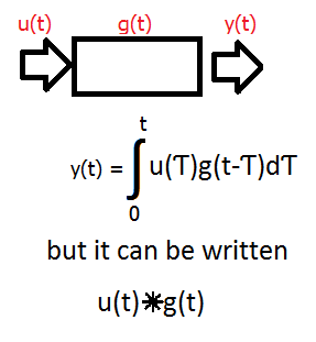
Ok. And back to a basic open loop transfer function example:
For explanation:
u(t) is the arbitrary input
g(t) is the impulse response
y(t) of curse is the output
If you take the Laplace transform of this system:
u(t) goes to u(s)
g(t) goes to G(s)
y(t) goes to Y(s) = u(s)G(s)
where G(s) is the transfer function
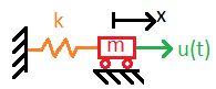
Ok. Let's go to an example to make it all easy:
This is a simple harmonic oscillator with mass 'm' and spring constant 'k'. It is subjected to an input forcing function u(t). The motion of this kind of system is:
ma(t) + kx(t) = u(t)
where a is the acceleration.
To find the system response we set u(t) to be equal the signal
u(t) = δ(t)
To solve this equation we need to use the Laplace transform, therefore let's do it using the above table:
ma(t) + kx(t) = δ(t)
m(s2X(s) – sx(0) – x'(0)) + kX(s)=1
we must remember that we don't have initial conditions therefore we have now:
ms2X(s) + kX(s) = 1
X(s)(ms2+ks) = 1
X(s) = 1/(ms2 + ks)
We have now the response function – and as it is called, the transfer function.
If you would need to go to the time domain you would need to get the inverse Laplace function for X(s). You need to find it in a table (it's not very easy to count). In this example it would be:
L-1(X(s) = 1/(sqrt(km)) sin (sqrt(k/m)*t)
If you look back to the long example with the remote controlled car, you can find this useful. If you could count all black boxes like in this example, and put the transfer functions in them, you could internally describe the reaction of the device. The equation would be the multiply of all transfer function from the path.