Continue to Site

Welcome to EDAboard.com

Welcome to our site! EDAboard.com is an international Electronics Discussion Forum focused on EDA software, circuits, schematics, books, theory, papers, asic, pld, 8051, DSP, Network, RF, Analog Design, PCB, Service Manuals... and a whole lot more! To participate you need to register. Registration is free. Click here to register now.

open loop and closed loop buck converter

Status
Not open for further replies.

eahmadi

Junior Member level 3
Joined
May 14, 2014
Messages
29
Helped
2
Reputation
4
Reaction score
2
Trophy points
3
Visit site
Activity points
200
Hi there,
I'm working on buck converter. I have got confused for differences between open loop and closed loop buck converter. I designed open loop converter.I have been considering a lot of parameters and trades of between them, such as output voltage ripple, inductor current ripple, switching frequency, load current,and like them. I have been spending much time on open loop buck converter, but for example, I can't have a good specific converter. Is it due to design closed loop? Am I right?
I look forward to hearing from you.
Thanks a lot in advance,
Ebi,
 

In an open loop design the output is not maintained constant as we dont check on its parameters like output current or voltage ......... but in a closed loop the output can be kept constant by increasing or decreasing the swithching freq. duty cycle. to maintain constant output.........
 

Thanks phobos1,
I'm a little in dark. Could you please explain clearly?
Thans in advance,
Ebi
 

In open loop converter, you simply have a fixed duty cycle to get the theoretically calculated output voltage. For example if the input is 10V and the output needed is 5 V, the duty cycle is fixed at 50% and there is no means of changing the duty cycle even if the output voltage falls below/above 5V (perhaps due to overloading or some other reason)
On the other hand, in a closed loop converter, the output voltage is continuously measured and fed back to the micro-controller. Depending upon the mismatch between the desired voltage and the actual output voltage, the controller adjusts the duty-cycle continuously. Therefore even if there is a mismatch due to some reason, the duty cycle is adjusted quickly to get the correct output.
 

To grasp the principles behind the buck converter, it helps to experiment with a simulator, especially an animated, interactive type.

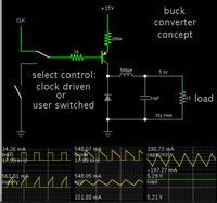
This is a tutorial circuit which I constructed, to demonstrate how a buck converter operates. You can control it yourself, or let the automatic clock drive it.


This is done in Falstad's simulator. It can export a link (below) which will:

(1) Open the site www.falstad.com/circuit
(2) Load my schematic into his simulator, and
(3) Run it on your computer.


To start a cycle, press the switch at left with your mouse.
For the second half of a cycle, let up the switch.

Watch the scope trace for the coil. Current rises during switch-On, and falls during switch-Off.

Watch how this action affects the output voltage. Eventually you will find the right tempo to click the switch on and off, so that you obtain a desired output voltage.

You can change values at will. Right-click on a component, and select Edit.

To save a schematic: Select File>Export, copy the text in the window, then paste it into a word processor, and save it from that program.
 

Status
Not open for further replies.

Part and Inventory Search

Welcome to EDABoard.com

Sponsor

Back
Top