Continue to Site

Welcome to EDAboard.com

Welcome to our site! EDAboard.com is an international Electronics Discussion Forum focused on EDA software, circuits, schematics, books, theory, papers, asic, pld, 8051, DSP, Network, RF, Analog Design, PCB, Service Manuals... and a whole lot more! To participate you need to register. Registration is free. Click here to register now.

opamp post layout simulation...

Status
Not open for further replies.

dipanjan

Member level 2
Joined
Sep 9, 2010
Messages
50
Helped
4
Reputation
8
Reaction score
4
Trophy points
1,288
Activity points
1,709
opamp post layout simulation... urgent very very urgent

hi i designed an opamp schematic....
on simulation the schematic is giving a gain of around 30dB
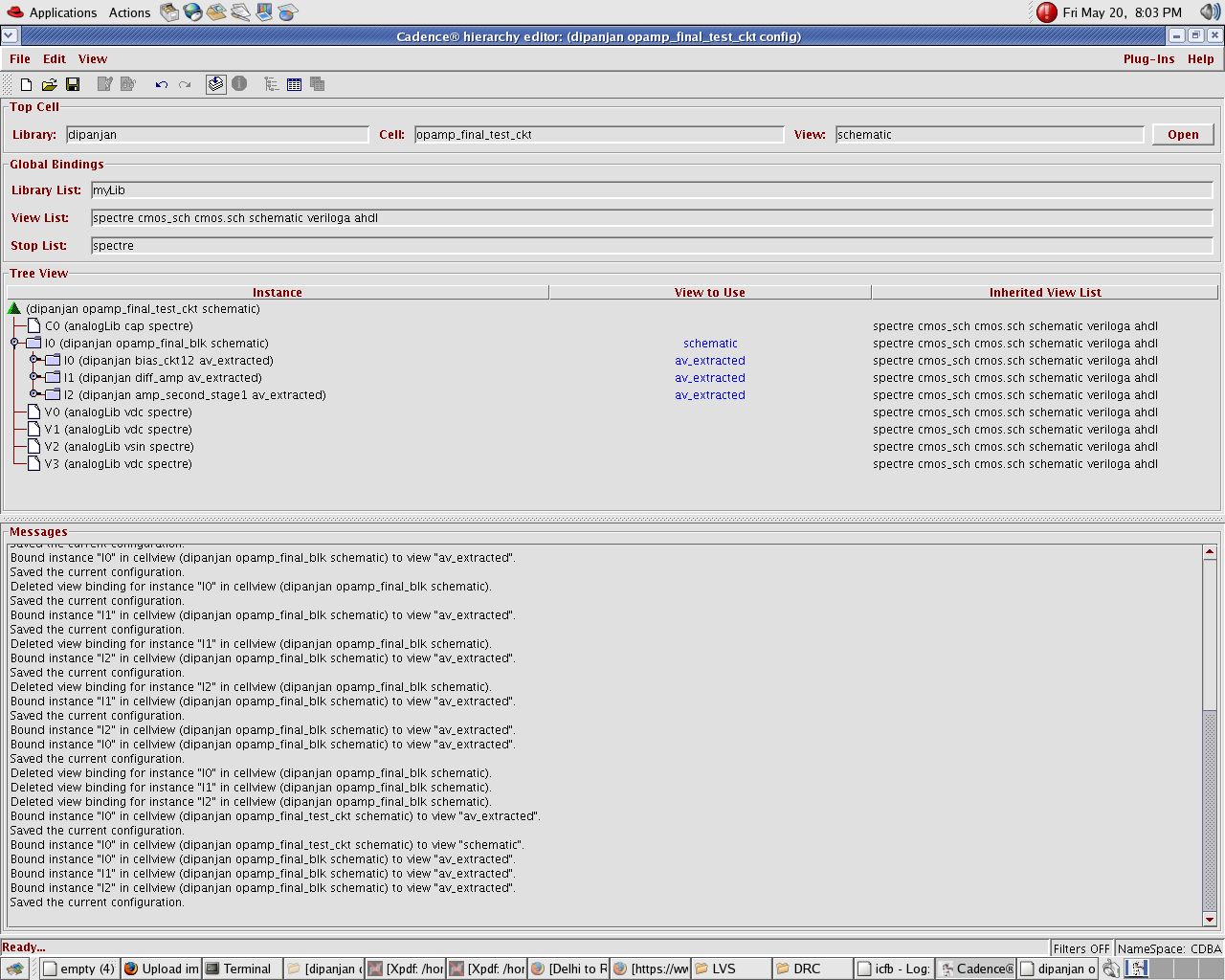
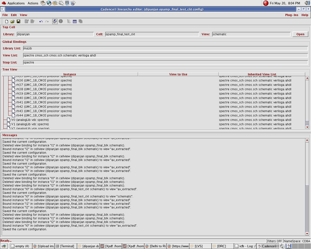
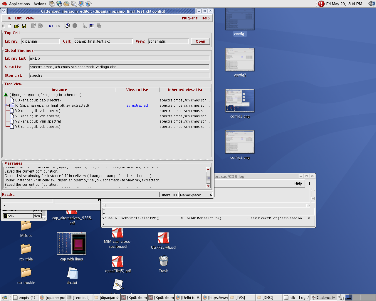
but after layout the post simulation result is bizarre....it is giving nearly 90dB....i was expecting tsome change in gain but how come the performances changed completely???.
how come it is increasing that too so much
any idea wat is happening??
 

I personaly would make sure that netlist with parasitics is correct.
You can start by extracting layout without any parasitics and re-simulate it. This should be exactly the same as schematic.
Then start adding parasitics and look at the netlist to make sure it is rght. Very often the netlist is messed up. Check all the grounds and powers. Make sure parasitics are connected to correct nodes.
It alwasy takes a bit time before the flow is fixed. Good luck


how do u extract a layout without parasitics....are you refering to simulation of the schematic??

---------- Post added at 23:13 ---------- Previous post was at 22:55 ----------

a closer look at the post layout simulation results suggests that after layout my compensation capacitance has become very very large.....i was using .5p but seems it has become a few hundred times more??
is it possible to generate that kind of parasitic cap....i am using nmoscap
i am using umc180 technology

can u suggest how i can create a netlist and look at the values of the diff pcaps generated in the ckt...


zooming in on the av_extracted isnt really helping


can i get numerical values listed in a netlist


can u generate that in cadence...plz help..really urgent need help
 

Guess you are using assura? I hate it so I use Calibre....
I think to prove the concept make something very simple -just inverter with moscap on output. That will show you what is wrong.
Av.extracted is a view no? And since you are able to simulate it you just go to ADE and view the netlist (simulation->netlist->display).
then compare it with schematic netlist.

To be honest i never used RCX assura. But this seems you might have issue with the PDK itself. Is there anybody who used it before? This might be a bit hard to debug like this.


no nobodywho worked on it around
 

Try to make the netlists and compare them.
You can contact UMC if it does not work - they should help if it is their PDK. Or contact whoever wrote the RCX extraction rules.
What could happen - and I saw it was that units in extraction or LVS deck were not set correctly. So schematic was using um and LVS/Extract deck were using meters.
Then it really messes things up.
 
Lot of good questions:

1. how do u extract a layout without parasitics....are you refering to simulation of the schematic??

Cadence offers a layout extracted view - that has devices with parameters from layout - however no interconnect parasitic with them.
This simulation result might be [I can't say "will be"] somewhat different from schematic - e.g. two independent MOS pcells if placed with S/D abutted - will increase AS,AD,PS,PD and some NRS NRD of MOS devices that in-turn would bring in some change is simulation characteristics. You will be able to isolate device parameter extraction problems versus RC extraction issues separately.

2. is it possible to generate that kind of parasitic cap....i am using nmoscap - i am using umc180 technology.

You mentioned - Hundred times? - sounds like miller cap - probably the coupling from input to output makes it - think of opamp with a cap coupling from out to inp or inm - and the effective capacitance.
Difficult to provide a point answer here, make sure canonical caps are not double counted [that means extracted again as if parasitic] - maybe check the RCXspiceINIT file [inside RCX tech dir] - tail it - and check for line with CAPGENOPTS - that shows Capgen compilation options used - check if your nmoscap device is blocked or not!

3. can u suggest how i can create a netlist and look at the values of the diff pcaps generated in the ckt...
Assura or QRC- RCX can generate SPICE, SPECTRE, xSPEF & xDSPF netlists for LVS-RCX flow, in addition to av_extracted view. So, you can always compare them.
Also check for - parasitic probing - that has good UI too. You can do a sum of C-lumped then Cc [coupling] 'net to net cap', then total parasitic R from point to point in a net and so on.

Teddy good points too.
 

Actually one more thing which goes wrong all the time.
Do you use "m" parameter in your mosfets? Quite often LVS can figure it out but during parasitic extraction it takes extracted value of whoele thing and multiplies it by m. - again extraction deck issue.
 
Lot of good questions:

1. how do u extract a layout without parasitics....are you refering to simulation of the schematic??

Cadence offers a layout extracted view - that has devices with parameters from layout - however no interconnect parasitic with them.
This simulation result might be [I can't say "will be"] somewhat different from schematic - e.g. two independent MOS pcells if placed with S/D abutted - will increase AS,AD,PS,PD and some NRS NRD of MOS devices that in-turn would bring in some change is simulation characteristics. You will be able to isolate device parameter extraction problems versus RC extraction issues separately.


how do i gnerate this view can u tell me the process to extact minus the parasites?

2. is it possible to generate that kind of parasitic cap....i am using nmoscap - i am using umc180 technology.

You mentioned - Hundred times? - sounds like miller cap - probably the coupling from input to output makes it - think of opamp with a cap coupling from out to inp or inm - and the effective capacitance.
Difficult to provide a point answer here, make sure canonical caps are not double counted [that means extracted again as if parasitic] - maybe check the RCXspiceINIT file [inside RCX tech dir] - tail it - and check for line with CAPGENOPTS - that shows Capgen compilation options used - check if your nmoscap device is blocked or not!

3. can u suggest how i can create a netlist and look at the values of the diff pcaps generated in the ckt...
Assura or QRC- RCX can generate SPICE, SPECTRE, xSPEF & xDSPF netlists for LVS-RCX flow, in addition to av_extracted view. So, you can always compare them.
Also check for - parasitic probing - that has good UI too. You can do a sum of C-lumped then Cc [coupling] 'net to net cap', then total parasitic R from point to point in a net and so on.

Teddy good points too.


i created the netlist... but not much help there are numerous pcap but te largest in order of 10^-14...seems that wont be that much..
i understand the miller part...the compensation cap is a miller cap but then shud not the same happen in schematic...due to input output coupling??
how does prasitics worsen the situation

---------- Post added at 06:55 ---------- Previous post was at 06:54 ----------

Actually one more thing which goes wrong all the time.
Do you use "m" parameter in your mosfets? Quite often LVS can figure it out but during parasitic extraction it takes extracted value of whoele thing and multiplies it by m. - again extraction deck issue.

no no multiplier

---------- Post added at 07:39 ---------- Previous post was at 06:55 ----------

hi can u tell me say if my parasitics related tothe nmos capis causing problem....in layout watis the standard procedure to reduce it...
which are the factors that contribute to capacitance
 

Try to make the netlists and compare them.
You can contact UMC if it does not work - they should help if it is their PDK. Or contact whoever wrote the RCX extraction rules.
What could happen - and I saw it was that units in extraction or LVS deck were not set correctly. So schematic was using um and LVS/Extract deck were using meters.
Then it really messes things up.


well help me with this...
you suggested simulating the layout as i do to the schematic before extraction...

so i went to the config cell view and made the layout instead of schematic or av_extracted as the simulated view and tried the simulations but it is unable to create any netlists at all

it says the netlist was never created before??
ne idea about it??

anyone who has used assura

can u tell me how can i simulate a layout.

i have simulated schematics and av_extracted views before so it seems logical that even before extraction the layout circuit should be possible to simulate it has the deevices and the connections i mean...
plz help out..
thank you in advance

---------- Post added at 11:42 ---------- Previous post was at 10:36 ----------

just got a bit more bizarre i have no clue...

i have designed a two stage opamp
so i have three blocks...
bias ckt
diff amp
and a pmos cs amp stage as 2nd stage


now i had made three blocks generated individual schematic and layout and extracted rc parasitics before i added the clocks in a single ckt...
i went on to form the entire layout


so now if i use the extraction from the final layout... i get this high gain low bandwidth

now on the otherhand if i use the schematic view of the final block and av extracted view of all the rest i get this low gain high freq output??????


now since layout of the devices dont change and what changes is that in the final layout i made wire connections so there should be a few more parasities due to metal
but layout of blocks and so i assume the parasites generated by them is same

then how cum the outpputs are diff

to help underatnd adding images
49_1305958133.png


---------- Post added at 11:43 ---------- Previous post was at 11:42 ----------

well help me with this...
you suggested simulating the layout as i do to the schematic before extraction...

so i went to the config cell view and made the layout instead of schematic or av_extracted as the simulated view and tried the simulations but it is unable to create any netlists at all

it says the netlist was never created before??
ne idea about it??

anyone who has used assura

can u tell me how can i simulate a layout.

i have simulated schematics and av_extracted views before so it seems logical that even before extraction the layout circuit should be possible to simulate it has the deevices and the connections i mean...
plz help out..
thank you in advance

---------- Post added at 11:42 ---------- Previous post was at 10:36 ----------

just got a bit more bizarre i have no clue...

i have designed a two stage opamp
so i have three blocks...
bias ckt
diff amp
and a pmos cs amp stage as 2nd stage


now i had made three blocks generated individual schematic and layout and extracted rc parasitics before i added the clocks in a single ckt...
i went on to form the entire layout


so now if i use the extraction from the final layout... i get this high gain low bandwidth

now on the otherhand if i use the schematic view of the final block and av extracted view of all the rest i get this low gain high freq output??????


now since layout of the devices dont change and what changes is that in the final layout i made wire connections so there should be a few more parasities due to metal
but layout of blocks and so i assume the parasites generated by them is same

then how cum the outpputs are diff

to help underatnd adding images
49_1305958133.png


---------- Post added at 11:43 ---------- Previous post was at 11:43 ----------


---------- Post added at 11:49 ---------- Previous post was at 11:43 ----------

sorry this one

 
Last edited by a moderator:

Hi,

In order to extract layout without parasitics of the interconnections you make in your layout,you should go to the Assura QRC setup (1st Tab) and instead of av_extracted view to be created you should select LVS extracted view.Nothing more to setup here for the creation of this view,so after this view is created you go to the Hierarchy Editor and choose the LVS extracted view for the cell you are interested in.

Another point...you can't simulate a layout view.When we say that we simulate a layout we mean that we are simulating it's respective av_extracted.So never choose layout from the Hierarchy Editor for your sims.

Far from setup images you provide little info about simulation results and target specs,so little help can be delivered to you.Pls give more details and maybe we can give you a hint.

Regards,
Jimito13
 

Hi,

In order to extract layout without parasitics of the interconnections you make in your layout,you should go to the Assura QRC setup (1st Tab) and instead of av_extracted view to be created you should select LVS extracted view.Nothing more to setup here for the creation of this view,so after this view is created you go to the Hierarchy Editor and choose the LVS extracted view for the cell you are interested in.

hi what ius QRC
i am using cadence 5.141 with umc 180nm technology and assura
in the assura drop down box i have drc lvs erc and rcx but nothing called qrc...
can u let me know how to run it?????

looking forward to it


Another point...you can't simulate a layout view.When we say that we simulate a layout we mean that we are simulating it's respective av_extracted.So never choose layout from the Hierarchy Editor for your sims.

Far from setup images you provide little info about simulation results and target specs,so little help can be delivered to you.Pls give more details and maybe we can give you a hint.

Regards,
Jimito13

thank you......when simulating schematic i got a gain of about around 20 dB and u3dB bandwidth of 200k and unity bandwidth of 4,5 M

however for av extracted of the complete schematic i have a gain as high as 70 dB and a very low bw.....

i choose to extract only cap and only resistance of the ckt and simulate
for only resistance i am getting very high gain but for only cap its is very low less than half of what i got through simulation of schematic

so i assume the problem is with resistance so i changed the interconnects in my layout from metal to poly

yet the drop in gain of av_extracted simulation is minimal...


on using av_extracted of bias ckkt...the current mirror of diff amp...the gain is more or less close to pre layout simulation...

remember when i am doing this i am omiting altogether the interconnect parasitics for the connection between the three blocks namely the biasing ckt..i.e the current mirror
the diff amp and the cs amp

but there is a huge drop in gain when i choose to use av_extrtact of cs amp stage

what parasite shud i b looking dfor to avoid this
 

QRC≡RCX.

I can't understand a lot of things from the way tou write.I am sorry...If possible give us two plots to start minimizing the problem :

1.The frequency response for the complete SCHEMATIC SIMULATION.
(the setup for the hierarchy editor should be : Top Level Cell Schematic and all sub-cells schematics as well)

2.The frequency response for the complete EXTRACTED SIMULATION(R+C and NOT R only or Conly).
(the setup for the hierarchy editor should be : Top Level Cell av_extracted)

In addition place markers on the plots for the DC Gain and Unity Gain Freq. or the 3dB freq.Do this and i will tell then the next steps.

I want to notice something : Are all your cells LVS clean??

lvs is clean.....i will be sending you the plots as u asked
 

Status
Not open for further replies.

Part and Inventory Search

Welcome to EDABoard.com

Sponsor

Back
Top