Continue to Site

Welcome to EDAboard.com

Welcome to our site! EDAboard.com is an international Electronics Discussion Forum focused on EDA software, circuits, schematics, books, theory, papers, asic, pld, 8051, DSP, Network, RF, Analog Design, PCB, Service Manuals... and a whole lot more! To participate you need to register. Registration is free. Click here to register now.

Opamp Output Problem

Status
Not open for further replies.

sdmuashr

Junior Member level 1
Joined
May 11, 2010
Messages
18
Helped
0
Reputation
0
Reaction score
0
Trophy points
1,281
Visit site
Activity points
1,448
Hi,

Background: The Opamp OPA547 is used in 2 identical but separate units of power supplies. One unit is functioning properly whereas the other one is defective. After comparison it was figured out that every pin of these two opamps has the same value/voltage except the input & output pins. There are 7 pins in the opamp.

Problem: The theory says that opamp just amplifies the difference in voltages applied at its input terminals. That is, if both inputs were of equal (i.e. 2mV & 2mV or 5mV & 5mV) values then the difference would be 0 and output would also be 0. However, what is noticed here is that one opamp with inputs (.6V & .6V) and the otherone with the inputs (0.9V & 0.9v) produce different outputs (instead of producing same voltage at the output). Please see the figure. Please also Keep in mind that all of the pins except for those mentioned in the figure are used but are not mentioned in the figure since they have the same values.
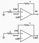
opamp.jpg

In case anyone interested further in knowing about the pin values then they are also mentioned in the following.
Opamp 1
1: 0.6v
2: 0.6v
3: -5V
4: -5V
5: 10.2V
6: 5v
7: -1.7V
Opamp 2 (Defective)
1: 0.9v
2: 0.9v
3: -5V
4: -5V
5: 10.2V
6: 7.3v
7: -1.7V
 

Problem: The theory says that opamp just amplifies the difference in voltages applied at its input terminals. That is, if both inputs were of equal (i.e. 2mV & 2mV or 5mV & 5mV) values then the difference would be 0 and output would also be 0.

That´s correct. However - in theory! That means: Ideal opamp units.
But because opamps are non-ideal units (they have a so-called offset voltage), the output in no case is zero for differential input of zero.
This is the reason for NEGATIVE feedback which allows a stable dc operating point.

In your text you do NOT mention any feedback - and in your figures you show POSITIVE feedback which inhibits stable amplifier operation.
Who has told you to try such a configuration?

The feedback is -ve. I made a mistake while drawing the schematic. However, what you say about the fact that same Opamp with two different sets of same input voltages (0.6V+0.6v & 0.9V+0.9V) provide different outputs. Shouldn't the output be same? That is, in order to get 5V for both opamps is it neccessary to apply 0.6V at the inputs of both opamps?
 

Hi,

you can´t measure the difference of IN+ and IN- in a regulating opamp because it is too low to show with a DVM.

Example:

OPA547 has an open loop gain of 115 dB. in other words: 560000.

To output 5V: the difference has to be theroretically 8.9uV
To output 7.35V --> 13uV
(all without taking offset and CMV into account)


0.900000 V and 0.900013V

Offset is typically 1mV, this means it is 77 times more than the theretically needed difference voltage.

Klaus

Edit/Added: Two about identical input voltages and the output not at the supply rails is a good indicator that the opamp is properly working. Your opamps are OK. ;-)
 

sdmuashr, you have forgotten to tell us which power supplies you are using (single or dual supply)?
 

sdmuashr, you have forgotten to tell us which power supplies you are using (single or dual supply)?
In his first post he shows all voltages. The positive supply is +10.2V and the negative supply is -5V.

With an input of 0.6V and an output of 5V to 7.35V then the voltage gain is low enough that input offset voltage does not matter. If both amplifiers have the same resistor values that set the voltage gain (he does not show these resistor values) then one amplifier is defective or is overloaded.
 

Hi,

i can´t see anything defective.

Both have about equal voltage gain: 8.2 and 8.3. (in further i calculate with 8.25)

To get an output voltage of 7.35V, you need 7.35V / 8.25 = 0.89V; rounded to one decimal is exactely the given 0.9V
To get an output voltage of 5V, you need 5V / 8.25 = 0.61V; rounded to one decimal is exactely the given 0.6V

All OK for me.


Klaus
 

In his first post he shows all voltages. The positive supply is +10.2V and the negative supply is -5V.
.

OK - may be. However, I am not motivated enough to go deeper into such a circuit without correct and sufficient information (wrong feedback, equal feedback resistors ?,...).
I don´t like guessing.
 

On the other website the OP admits that the circuits are identical but the malfunctioning opamp has a higher input voltage of 0.9V and the good opamp has an input of 0.6V.
So obviously the opamps are fine and the signal source that has a voltage too high is defective.
 

Status
Not open for further replies.

Similar threads

Part and Inventory Search

Welcome to EDABoard.com

Sponsor

Back
Top