Continue to Site

Welcome to EDAboard.com

Welcome to our site! EDAboard.com is an international Electronics Discussion Forum focused on EDA software, circuits, schematics, books, theory, papers, asic, pld, 8051, DSP, Network, RF, Analog Design, PCB, Service Manuals... and a whole lot more! To participate you need to register. Registration is free. Click here to register now.

OPAMP for the active filters

Status
Not open for further replies.

ananthesh bhat

Junior Member level 3
Joined
Mar 8, 2013
Messages
31
Helped
1
Reputation
2
Reaction score
1
Trophy points
1,288
Activity points
1,514
Hello All,

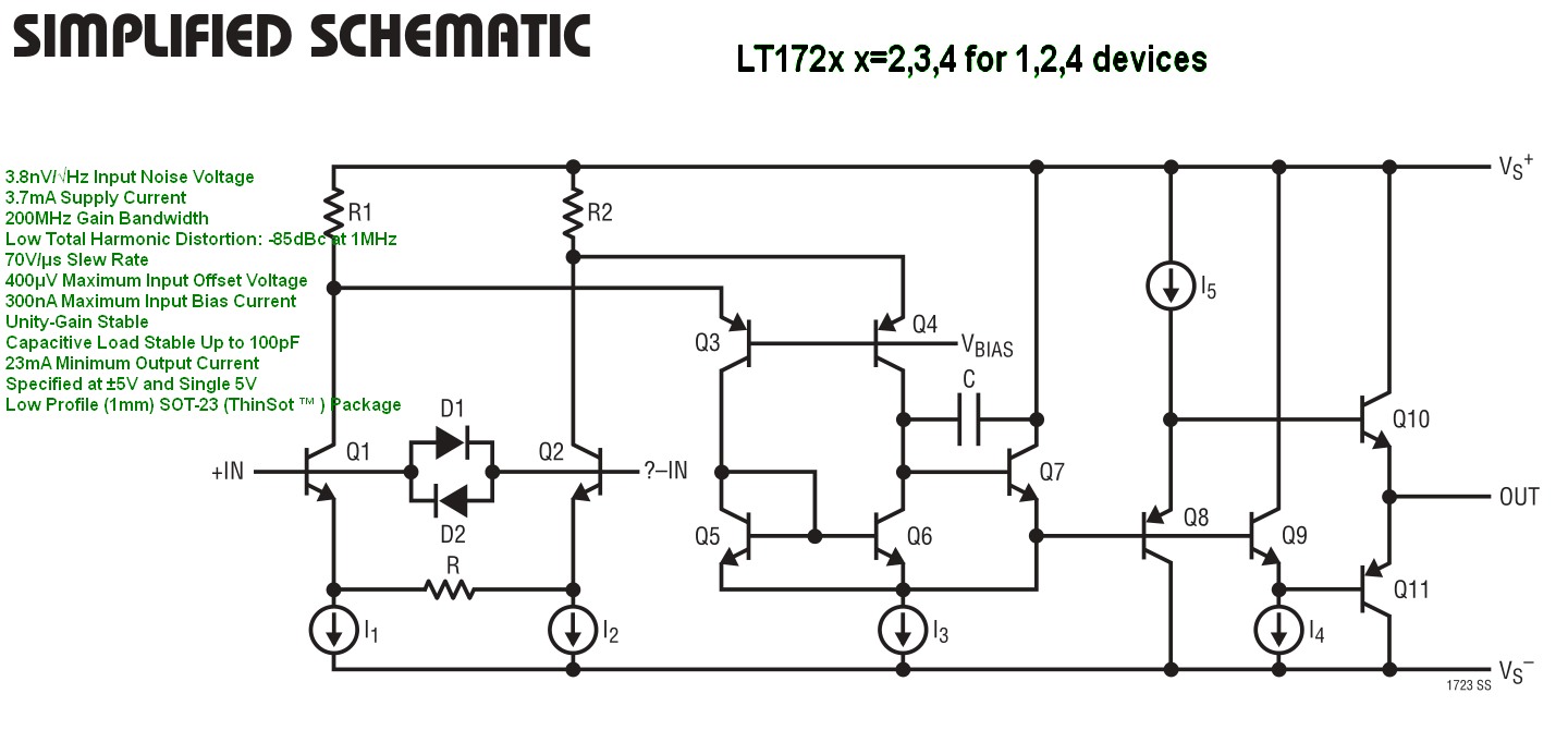
I'm designing a Sallen-Key low pass filter with a cut-off frequency as 10MHz. For this filter, I'm designing an OPAMP which is single stage folded cascode (as folded cascode is preferred for the unity gain configuration and I need this unity gain configuration for the Sallen-key).

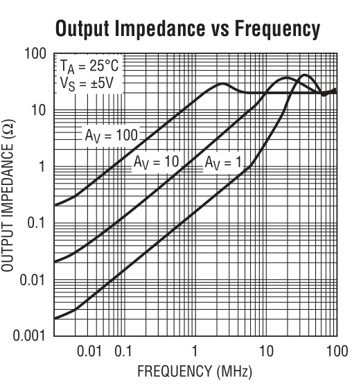
The problem with the Sallen-key topology is, for the higher frequencies the output impedance of the OPAMP tend to be significant in increasing the stop band signal strength, which is not desirable. So, I want to decide upon the buffer stage to cascade with my folded cascode stage to avoid the above mentioned problem. Is one common drain amplifier is sufficient to realize the buffer or are there any other topologies which will be of more benefits to have lower output impedance.
 

Is one common drain amplifier is sufficient to realize the buffer or are there any other topologies which will be of more benefits to have lower output impedance.

You can try, but I don't think a source follower is a good solution: it changes your DC output voltage (about Vth), and it usually has very different sink and source, as well as slew-rate capabilities. If this is fine for your application, ok. Otherwise I'd prefer a class-AB output stage, which of course is a bit more complex, s. e.g. this circuit : class-AB_output-stage.png

BTW: Both configurations introduce a further pole!
 

I have one more concern in designing the opamp. If the cutoff frequency of my filter is 1MHz, then should I design an opamp which is GBW as 100*cutoff frequency?
 

Hi,

10MHz or 1MHz cutoff frequency?

Cutoff frequency x 100 is a good value to start.
It depends what precision in output you need. If you need low THD, low output impedance, good precision in gain, then increase value.
If it is not that problematic, then you can reduce it.

Klaus

- - - Updated - - -

Hi,

is passive (R)LC filtering an option?

Klaus
 

2711924400_1429773537.jpg
Why reinvent the wheel? Figure out how it is already done.

7465165100_1429773049.jpg


Then realize the source impedance must be much lower (<<10%) than the selected impedances for the filter feedback, no matter how high it is.

This one has 3 stages of buffering.
 

Hi,

10MHz or 1MHz cutoff frequency?

Cutoff frequency x 100 is a good value to start.
It depends what precision in output you need. If you need low THD, low output impedance, good precision in gain, then increase value.
If it is not that problematic, then you can reduce it.


Hey,
For the filter I'm designing, the cutoff frequency is 1MHz, 5MHz and 10MHz. I will come up with a logic to tune the cutoff frequency and that is not a problem. The problem lies in designing the OPAMP for this particular frequency application.

To realize this filter with sallen-Key, I should have an opamp with GBW as 100xFc, which is 1GHz. Is this correct?

Should I design an opamp with very low impedance and with GBW as 1GHz?

Also, to mention, my power specification is 20mW and IIP3 is 20dB.

Please help me with this.

- - - Updated - - -

2711924400_1429773537.jpg
Why reinvent the wheel? Figure out how it is already done.

7465165100_1429773049.jpg


Then realize the source impedance must be much lower (<<10%) than the selected impedances for the filter feedback, no matter how high it is.

This one has 3 stages of buffering.

Hey Sunny,
Using three stages of buffering will not affect the stability of the system?
 

Hi,

with the hardware design i can´t help.

but what about a passive solution?

Klaus


Hi,

with the hardware design i can´t help.

but what about a passive solution?

Klaus

Hey,

What do you mean by passive solution here? You would like to include inductor with the opamp?
 

Hi,

What do you mean by passive solution here? You would like to include inductor with the opamp?

It is just a question. Passive = not active = without OPAMP, just R, L, C.

I know you are designing an IC, and i don't know what L and C size is possible.
External components may increase pincount, partcount, and so on...

Especially sallen key low pass filters are critical with OPAMP GBW and may not give the expected attenuation at high frequencies.

Klaus
 

Hi,


It is just a question. Passive = not active = without OPAMP, just R, L, C.

I know you are designing an IC, and i don't know what L and C size is possible.
External components may increase pincount, partcount, and so on...

Especially sallen key low pass filters are critical with OPAMP GBW and may not give the expected attenuation at high frequencies.

Klaus

Yes. I understand. But I cannot afford to use Inductor in my design because of area constraints. Do you suggest any other topology for 10MHz cutoff frequency? I went through quite a lot of articles and concluded that Sallen-Key is the best topology for high frequency application. I cannot go with MFB topology as OPAMP used in the MFB topology acts as integrator and design will be very difficult in high frequency.
 

Hi

... MFB topology acts as integrator ...
In both topologies there are resistors and capacitors that work beyond cutoff frequecy similar to integrators.

I may be mistaken, but afaik the MFB topology has improvements in high frequency attenuation compared to sallen key.
But to be honest, i'm not experienced with filters in that frequenciy area.


Klaus
 

Tow Thomos biquad??

Be it any topology, you need not design an amp having GBW 100 times your filter bandwidth as it may be an overkill. The GBW is chosen based on the allowable pass band ripple (there are techniques to trim the Q of a filter just like changing the BW from 1MHz to 5MHz and so on). This can be accurately calculated in matlab smualtions. The in-band distortion performance depends on the open loop gain of the system at that frequency. So, having a decent gain of 30-35 dB till 10MHz (if fc is 10MHz) is good enough.
 

Hi

To me it seems that GBW of an OPAMP is mixed up with Q-forming gain of a feedbacked active filter.

Btw: 30-35dB is not that far away from gain of 100. It's well within the tolerance is of GBW of an OPAMP.

Klaus
 

I may be mistaken, but afaik the MFB topology has improvements in high frequency attenuation compared to sallen key.
But to be honest, i'm not experienced with filters in that frequenciy area.

Klaus

Yes - that´s true. It is a known fact, that the positive Sallen-Key low pass structure shows an unwanted output increase in the stop band for rising frequencies. This results from the direct coupling of the input signal to the output via the feedback capacitor. Other topologies (MFB, GIC) have much better behaviour in this respect.
 

Status
Not open for further replies.

Part and Inventory Search

Welcome to EDABoard.com

Sponsor

Back
Top