Welcome to our site! EDAboard.com is an international Electronics Discussion Forum focused on EDA software, circuits, schematics, books, theory, papers, asic, pld, 8051, DSP, Network, RF, Analog Design, PCB, Service Manuals... and a whole lot more! To participate you need to register. Registration is free. Click here to register now.
Hi Friends can u help me to find which config of opamp is used in this circuit . i think its error . Please help me to design the compensation circuit .
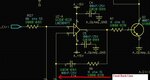
The clue is the input on the left labelled "Ctrl" which is the set point.
If so, there should be another resistor just off the circuit down near and just beyond where the red arrow is.
R6 and the missing resistor set proportional gain, and C24 sets the integral time constant.
It has nothing to do with op amp compensation, but for tuning of the control loop to suit whatever this is trying to control.
Presumed there's a resistor to ground completing the feedback network, it's an amplifier with PI characteristic and surely a valid OP configuration. You should show the complete OP circuit.
The point that may confused you is that due to the integrator behavior, the circuit needs an external feedback loop to reach a stable non-saturated operation point. In case of a PI controller, the loop is closed through the control process.
hai friends please check the circuit please help me to solve the highlighted portion . i would like to know design of feedback loop and which config of opamp . also why they use fixed bias for driving the darlington pair
The darlington and the common emitter transistor driving it is just a very high gain current multiplier. Its not fixed bias, but bias is controlled by the current through the transistor.
The output current into the load is monitored by a current shunt, and that provides feedback back into the proportional integral error amplifier.
The control input at the upper left sets the desired current through the load, and the feedback amplifier ensures that those conditions are met.
The error amplifier need to be correctly tuned for both gain and phase, to obtain best transient response and stability.
If its not tuned correctly, the circuit may either have a very sluggish response to rapid input changes, or it may overshoot, and become unstable, even oscillate.
If you feed an appropriate frequency square wave drive signal into the input, and monitor the load current with an oscilloscope, that will tell you all you need to know about how well the feedback amplifier is working, or what may be wrong with it.
Can i say this is basically error amp . When i check for integrator we always gives vin at -ve terminal, where as in error its in +ve terminal similar to this cofig . if so how can i design this resistor , capacitor comb in feedback loop of opamp . for designing what all spec we need and how to design
These are essentially two related questions:
- How to chose the feedback loop parameters for the constant current source?
- How to implement the parameters with the shown circuit
For the first part, the PI error amplifier has basically two parameters, proportinal gain KP and integrator time constant TI. Assuming a control process with poles (PTn), the loop becomes instable if KP is increased, you'll chose the maximal value with no oscillations and acceptable overshoot. Then select the smallest KI that doesn't reduce loop stability.
The shown circuit has current dependent gain, so you have to try with different current settings. Most likely highest current is the critical case here. Loop gain and poles can be derived by circuit analysis, but tuning the parameters empirically may be easier. In case of doubt you can use Ziegler-Nichols tuning method. https://en.wikipedia.org/wiki/Ziegler–Nichols_method
The other point is how PI parameters are set in the OP circuit.
Quite simply you get KP = R6/R129 and TI = R6*C24.
Actually i need to drive a load of 0.5amp to 2amp with constant Current and varying Voltage which depends upon the Load say max 15Volt . and the set voltage will vary form 0 to 4.1Volt from DAC . This is the condition .
In this case how to start design of opamp .Which conditions we need to assume. in this condition. do i need to find the loop gain first and poles . Can u guide me to do this . plz
Derivative action is not appropriate for many (most) control systems because it often introduces more problems than it solves.
Generally it is helpful only where load response is extremely slow and the system greatly underpowered.
It is not possible to fully analyze or simulate a system like this unless you can define all the operating parameters precisely.
For instance, what is the precise current gain of your darlington, and the transistor driving it ? How will normal component spreads effect this ?
How does temperature effect that ?
Unless you can nail that down, you cannot even begin to work out what proportional gain might be needed in the error amplifier.
As far as integral time constant goes, what kind of load is this ?
Is it a motor or an inductive load with some hidden resonances or inertia that is going to hugely effect the phase and current through the load ?
Only way to approach this is to build it and test it, and then try to figure out what kind of gain and phase response the error amplifier needs to have.
A Bode plot of the whole thing might be a good start.
Seeing how it responds to step input changes might also be quite revealing.
This site uses cookies to help personalise content, tailor your experience and to keep you logged in if you register.
By continuing to use this site, you are consenting to our use of cookies.