Continue to Site

Welcome to EDAboard.com

Welcome to our site! EDAboard.com is an international Electronics Discussion Forum focused on EDA software, circuits, schematics, books, theory, papers, asic, pld, 8051, DSP, Network, RF, Analog Design, PCB, Service Manuals... and a whole lot more! To participate you need to register. Registration is free. Click here to register now.

opamp amplifier for ADC

Status
Not open for further replies.

dmta

Member level 2
Joined
Mar 25, 2013
Messages
52
Helped
0
Reputation
0
Reaction score
0
Trophy points
1,286
Location
Earth
Activity points
1,650
Hi all,

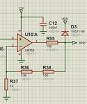
I have to amplify a voltage signal and read it into a microcontroller. For this I am using the following circuit. R55 and D3 are for clamping the input if it goes beyond 5V.

I had previously connected R38 to the output of the opamp but now decided to connect it between R55 and D3 to compensate for any voltage drop across R55.

My question is will this have any other good or bad effect that I am not seeing?

Regards FRM.JPG
 

I had a similar interface issue which might help with your thoughts (and mine!)

My input was from an opamp powered by +/-10V hence presenting a bipolar input to the A/D of an mBed module which operates over 0 to 3.3V input but 5V tollerant.

My circuit was similar in design except I had another diode to clamp the input at -0.6V.

I decided to take the feedback from the opamp output so that the opamp remained in the linear range, irrespective of what happens with the clamp diode(s).
I also had my equiv of R55 at 10K. My reasoning is that as the input to the A/D is high impedance this will not introduce any significant error.
Also when the clamp diodes operated the output of the op amp was not excessively loaded (approx 10mA) and again it remined in the linear range of the opamp. Saturation of the opamp output can cause all sorts of unusual behavious, such as long delays when recovering and signal inversions causing latch up in FET input devices.
My solution will cause a HF roll off due to the 10K R55 value, but its effects are way outside my acquisition frequency.

For your circuit, in the 'normal' operating range, I don't think R55 will cause any errors with the measurements, but I would examine what happens at the point the circuit clamps and how it recovers.
 

Status
Not open for further replies.

Similar threads

Part and Inventory Search

Welcome to EDABoard.com

Sponsor

Back
Top