Continue to Site

Welcome to EDAboard.com

Welcome to our site! EDAboard.com is an international Electronics Discussion Forum focused on EDA software, circuits, schematics, books, theory, papers, asic, pld, 8051, DSP, Network, RF, Analog Design, PCB, Service Manuals... and a whole lot more! To participate you need to register. Registration is free. Click here to register now.

Op Amp voltage input question

Status
Not open for further replies.

rameshrai

Full Member level 3
Joined
Aug 16, 2010
Messages
158
Helped
7
Reputation
14
Reaction score
7
Trophy points
1,298
Activity points
2,272
Hi.

I am simulating op amp 741 configured as unity gain inverter in proteus. When the signal input is ac signal with 10mV amplitude the output signal is ok but when the amplitude is 1V I get distorted output waveform as shown in the figure(2) below. Can anybody explain how to correct this?
opamp.png
graph.png

Thanks!
 

What is the input signal frequency?
 

maybe you should increase 1K to 10K or more. Input current is 1V/1K=1mA, is this too big for your OpAmp?
And OpAmp input has some capacitors, that can cause hyperthesis effect.
 

It's long time since I used a uA 741, My recollection is that they need compensation. See the data sheet.

I suspect that is why you're seeing a high frequency oscillation at the top & bottom of the sine curve.

- - - Updated - - -

maybe you should increase 1K to 10K or more. Input current is 1V/1K=1mA, is this too big for your OpAmp?
And OpAmp input has some capacitors, that can cause hyperthesis effect.

There is no problem with 1 K resistors.

The negative feedback causes the voltage at the negative input to be almost equal to the voltage at the positive input.

Therefore, there is virtually no current going into the negative input (except for the bias current).

Most of the current passes from one resistor to the other.
See the attached diagram.
 

Attachments

  • Op Amp.jpg
    Op Amp.jpg
    316.6 KB · Views: 141

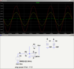
Here's an LTspice simulation of your circuit for inputs of 0.1V, 1V and 2V.
The output for all input amplitudes looks fine.
I can think of no reason why you should see the strange waveform you observed, unless there's some problem with your 741 model.
You might try a different op amp model to see how that works.

741 Demo.PNG
 

Hi.

I am simulating op amp 741 configured as unity gain inverter in proteus. When the signal input is ac signal with 10mV amplitude the output signal is ok but when the amplitude is 1V I get distorted output waveform as shown in the figure(2) below. Can anybody explain how to correct this?
opamp.png
graph.png

Hi
I don't see any reason for that ! i just think it's problem of the simulation model of the op amp in your simulator or perhaps your simulator !

Best wishes
Goldsmith
 

The 12v and -12v connected to the circuit. Are they defined in the power configuration. I would rather place a voltage generator and change the magnitude to 12v and -12v. I am guessing proteus is applying 5v to your IC and not the 12v you labelled it
 

Your blue trace might be your output. It shows oscillation at about 24kHz on its positive and negative peaks of the 2kHz sinewave and it shows severe crossover distortion at its middle.
An old 741 opamp does not oscillate when it is wired neatly and it has no crossover distortion so your simulator is messing it up. Build it to prove it.
 

- the resistor value are fine because i already did try 10k and even other resistor values
- compensation i didn't try because i thought this would not be much of a problem
- I tried other 741 op-amp in proteus(eg. LM741) which gave me the same problem
- simulation model problem? Most of the parts have been working fine except these uA741, LM741 at this inverter configuration
- I don't think that there is problem with the voltage supply, i have always used these ways

@audioguru i don't understand what you mean?

i think i should give the compensation part a try

- - - Updated - - -

the op amp is now working fine, after few days. what happened was that the op-amp output was left connected to a transformer. whereas i was sure i tested the op-amp without any loads thats why i had no idea why it was showing that kind of graph. does proteus remembers previous simulation?

thanks all
 
Last edited:

Your 'scope photo was confusing:
1) None of the 4 traces showed what they were. Which trace was input, which was output and where are their 0V?
2) Nothing shows how many volts.
 

hi,

@audioguru your comment led to me to rethink that i did some mistake in my schematic. thanks for that. The problem is solved as I said. Regarding traces, I thought it was obvious. The yellow was the input signal and the blue was the distorted output and the other two were not used. But I should have clarified this too.

thanks again
 

Your 'scope photo would tell us a lot of you connect one unused channel to 0V and mark it on the photo. Also tell us the volts per grid line.
 

Status
Not open for further replies.

Similar threads

Part and Inventory Search

Welcome to EDABoard.com

Sponsor

Back
Top