Continue to Site

Welcome to EDAboard.com

Welcome to our site! EDAboard.com is an international Electronics Discussion Forum focused on EDA software, circuits, schematics, books, theory, papers, asic, pld, 8051, DSP, Network, RF, Analog Design, PCB, Service Manuals... and a whole lot more! To participate you need to register. Registration is free. Click here to register now.

OP-AMP Schematic Help

Status
Not open for further replies.

kiwi101

Newbie level 6
Joined
Apr 23, 2015
Messages
12
Helped
0
Reputation
0
Reaction score
0
Trophy points
1
Activity points
69
Hey guys,

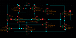
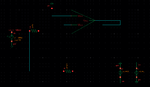
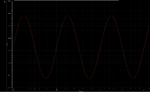
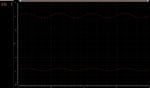
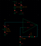
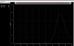
I'm trying to make a triangle wave generator circuit on cadence but in order to do that I have to make an OP-AMP first. This is the schematic I made for the OP-AMP and when I plot the Vout vs t or Vin vs t, it's clear to see that something is off.
Any suggestions are appreciated.
 

Attachments

  • Schematic.png
    Schematic.png
    29.5 KB · Views: 92
  • Circuit.png
    Circuit.png
    13.6 KB · Views: 81
  • Plot.png
    Plot.png
    30.3 KB · Views: 71

The Vsource V0 has a generator impedance of 0Ω, hence the output in your circuit is a superimposition of the (negative) open-loop amplified input signal and the (positive) input signal itself, fighting against each other via their generation impedances.

R1 should connect to Vin- for an (intended?) closed loop gain = -2 .
 

So for the Vsource
I set the amplitute to 100 mV and the frequency to 1K so what do you mean by the generator impedence? Should I change it?

Thanks I changed the R1 can't believe I missed that. But my graph is still pretty much coming the same surprisingly

- - - Updated - - -

Here is what I got after changing the R1 to connect to Vin - and yes my intended closed loop gain is -2

- - - Updated - - -

Okay so I went back and changed some things in the Schematic of my opamp and now Im getting a gain. However the gain for Vout is not centered at the same place for the gain of Vin. Could someone tell me how I should current bias the Diff amp fo my op-amp to the gain part of my opamp.
 

Attachments

  • plot1.png
    plot1.png
    23.9 KB · Views: 75
  • Schematic1.png
    Schematic1.png
    10.3 KB · Views: 84
  • plot2.png
    plot2.png
    27.9 KB · Views: 74
  • Circuit1.png
    Circuit1.png
    25.5 KB · Views: 74

If I interpret your wave outputs correctly, your amp doesn't show any gain. Probably your DC input voltage isn't within the correct ICMR. Check your node voltages and if the MOSFETs work in saturation region.

Strange: there is a 2V DC difference between output and input. Seems there's a 2nA leakage current over the 1GΩ feedback resistor.
 

Status
Not open for further replies.

Part and Inventory Search

Welcome to EDABoard.com

Sponsor

Back
Top