mat_lab_trin
Newbie level 3
I posted a problem with an op-amp amplification last month and I did not posted enough information.
Now I include the circuit diagram and the result I got.
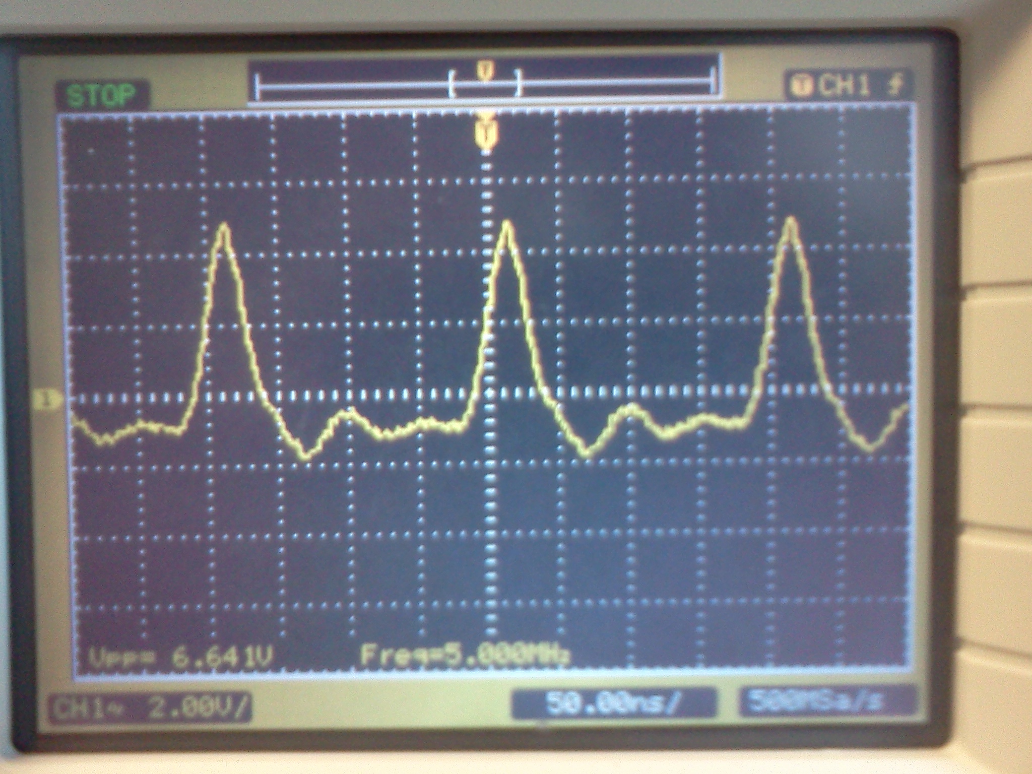
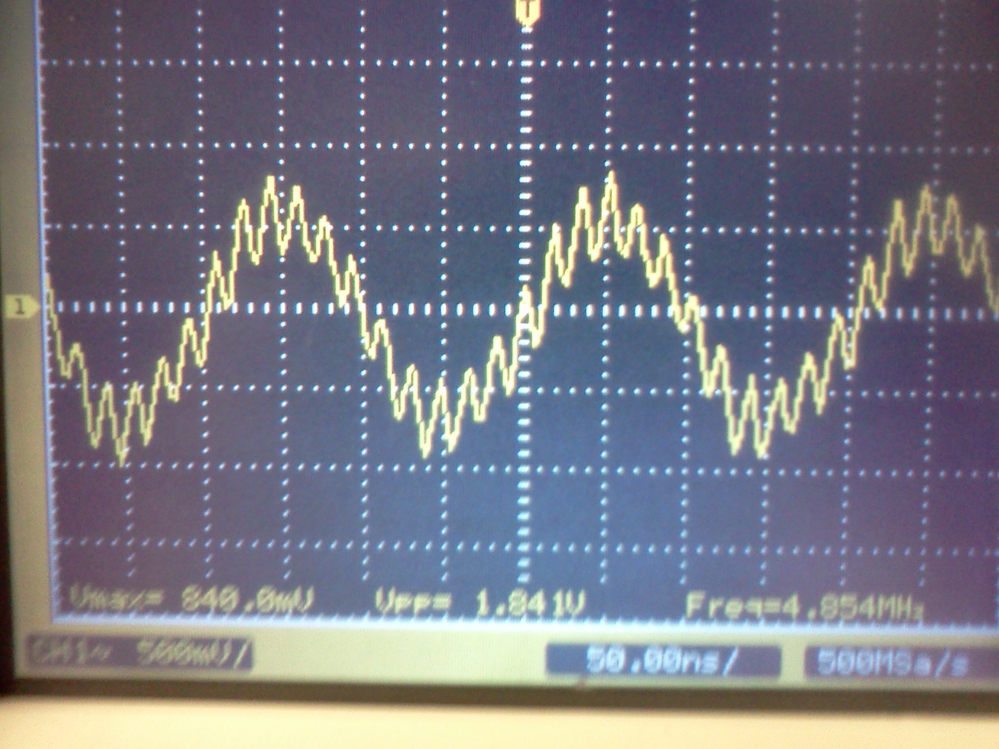
I used LT1226 op-amp with Vss=+10V. the input was the sine wave generate from the function generator (Vp-p = 2V, f = 5MHz, DC offset V=0V).
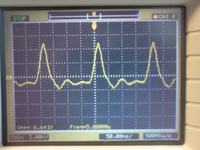
I connected the output pin to Oscilloscope and I got the result shown in the attached picture.
I want to amplify 20-40mV at 5MHz frequency. If anyone has any suggestion on how to do that, please post it as well. Thank you.
Now I include the circuit diagram and the result I got.
I used LT1226 op-amp with Vss=+10V. the input was the sine wave generate from the function generator (Vp-p = 2V, f = 5MHz, DC offset V=0V).
I connected the output pin to Oscilloscope and I got the result shown in the attached picture.
I want to amplify 20-40mV at 5MHz frequency. If anyone has any suggestion on how to do that, please post it as well. Thank you.