Welcome to our site! EDAboard.com is an international Electronics Discussion Forum focused on EDA software, circuits, schematics, books, theory, papers, asic, pld, 8051, DSP, Network, RF, Analog Design, PCB, Service Manuals... and a whole lot more! To participate you need to register. Registration is free. Click here to register now.
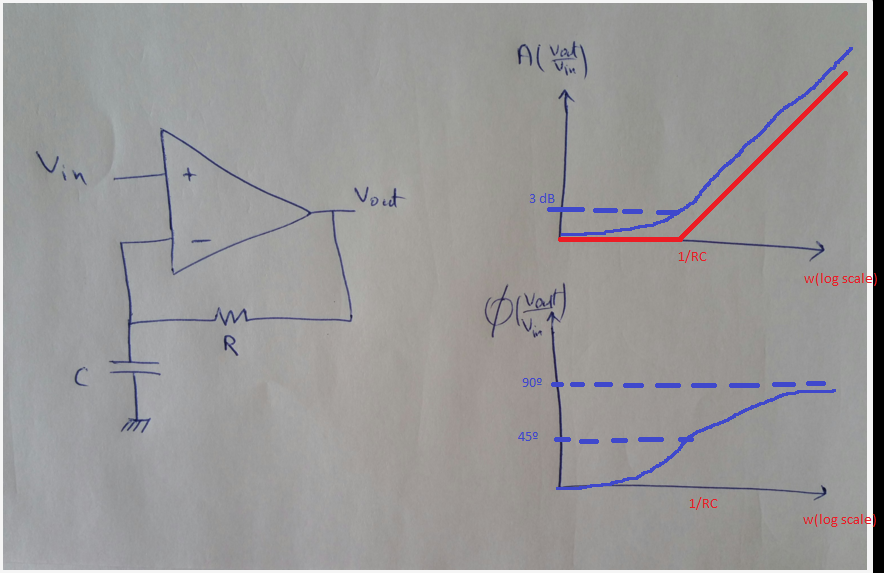
Vout(s)/Vin(s)=1+RCs assuming no initial conditions. The transfer function is a simple "real zero" which is represented in Bode plot like I drawed. When ω=1/RC the amplitude is sqrt(2) and in dB is 3 dB.
When ω<<1/RC amplitude is ≈1 meaning 0 dB.
When ω>>1/RC amplitude rises with +20 dB/dec.
If ask me more specific question, I know where to focus...
This site uses cookies to help personalise content, tailor your experience and to keep you logged in if you register.
By continuing to use this site, you are consenting to our use of cookies.