Continue to Site

Welcome to EDAboard.com

Welcome to our site! EDAboard.com is an international Electronics Discussion Forum focused on EDA software, circuits, schematics, books, theory, papers, asic, pld, 8051, DSP, Network, RF, Analog Design, PCB, Service Manuals... and a whole lot more! To participate you need to register. Registration is free. Click here to register now.

Op-amp design Question

Status
Not open for further replies.

baby_1

Advanced Member level 1
Joined
Dec 3, 2010
Messages
415
Helped
1
Reputation
2
Reaction score
1
Trophy points
1,298
Activity points
4,277
Hello
i want to work with op-amp as my first test
i have some question:
in ad822 that work in 5-30volt in single mode , can i powered it up with +15 and -15 (dual supply that voltage=15-(-15)=30 )?

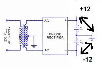
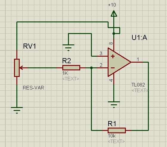
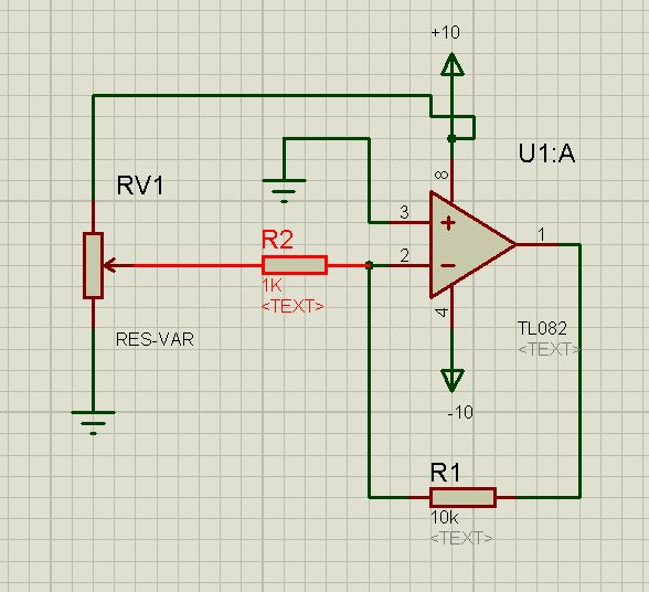
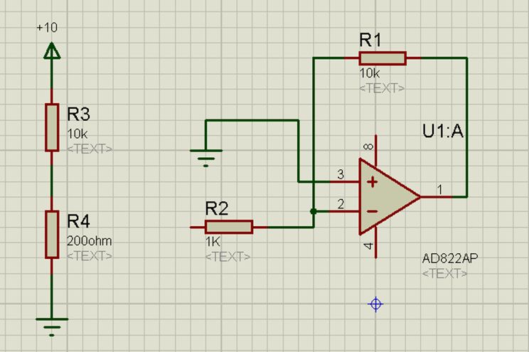
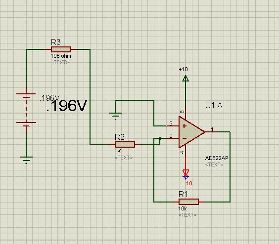
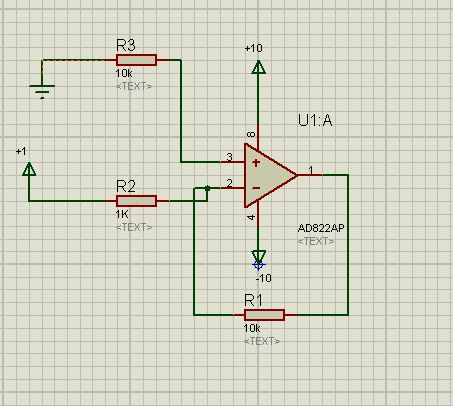
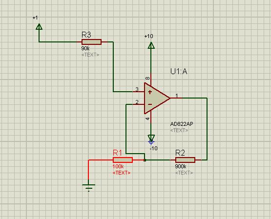
i tested it with a dual supply voltage (+12 -12) and with this schematic
2062060900_1352834711.jpg

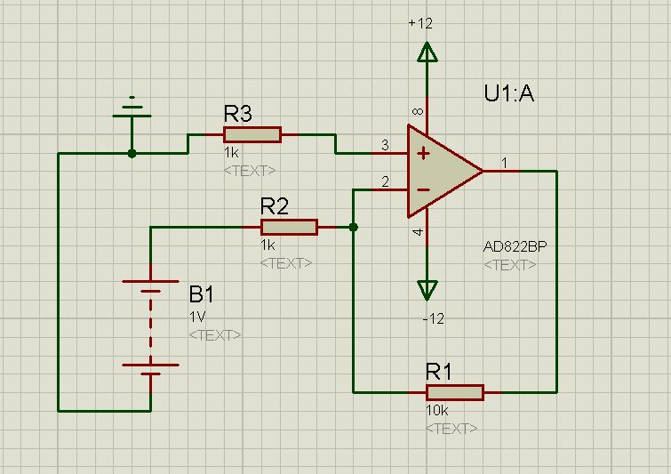
but i take 22 volt in output instead of 10 volt(1Volt * 10) , why? if a op-amp want works fine the output should be between VCC and -VCC not 2VCC to ground ?

what is my fault?
 

Question: Are both supply sources referenced to ground (in the middle between both sources)?
 

Thanks friends
yes my wiring is correct as i check more than 5 times.
here is my power supply
1286846300_1352871812.jpg
 

Something is seriously wrong if you get 22V out with a 12V supply! Have you checked your power supply voltages? A 12V transformer will give a lot more than 12V out if you simply rectify and smooth it without a regulator. I suspect you opamp is toast.

Keith
 

I checked it a lot
V out=+11.5 and -11.5 to ground
now i change my op-amp to Tl082 with this schamtic
3497878100_1352885296.jpg

i set the output voltage of Pot about .1 to .5 but the output of this circuit is about 8.7-8.9 !!!!! why?
i change my adapter with a dual power supply (-10 +10 ground) and give to my circuit
5629605500_1352885297.jpg

but still my output voltage via .1 to .5 volt is about 8.7-8.9

the correct value as i calculate should be 1 to 5 volt not 8.7 to 8.9

what is my fault?
 
Last edited:

but still my output voltage via .1 to .5 volt is about 8.7-8.9
the correct value as i calculate should be 1 to 5 volt not 8.7 to 8.9
what is my fault?

For a gain of 10 and an input voltage of 0.1 to 0.5 volts the output assumes 1...5 volts if the input voltage is a real voltage SOURCE.
But in your case it is the pot, which influences the gain because it changes the feedback factor.
Instead, use a real voltage source and measure again.
By the way: Are you speaking about measurement data or simulation results?
 
  • Like
Reactions: baby_1

    baby_1

    Points: 2
    Helpful Answer Positive Rating
Thank you very much LVW
i test and it works fine with a real source (i created a 2.5 volt via TL431 and inject to my op-amp)
another question is we calculate the Gian of op-amp only in dc mode ? correct ( as i read in electronics book in university) ? if i add a cap , microphone to my circuit such as this circuit
6968640000_1352896503.jpg

can these elements change the gain of op-amp such as transistor in AC analyses?
Thanks


By the way: Are you speaking about measurement data or simulation results?
Dear LvW i do it in reality not as a simulation
 

The circuit doesn't work with single supply, a positive bias for noniverting input would be needed, e.g. a voltage divider.

Are you designing OP circuits at will?
 

My comments in post#7 apply
* for split supply only, and
* in case the input voltage is determined without the amplifier (R2) connected.
 

Thanks dear FVM and LvW
sorry i forget that i should use dual power supply for my op-amp , now if i use dula power supply .... continue post #8
 

Dear LVW
yes my first problem has been solved by adding the real source voltage instead of resistor divider network
now i want to know is op-amp similar transistor in AC analyses
6968640000_1352896503.jpg

that the new components such as capacitor microphone and pull up-resistor can change the gain of op-amp? or our gain only calculate in DC analyses?
 

Hello Again
i have a question about my first problem that solved when i remove the resistor divider network and set voltage directly to R1 in this schematic
5629605500_1352885297.jpg

in this schematic
7989987400_1352914051.jpg

AV=R(feadback)/R(-)=10k/1k=10
that is the same the above it circuit (i want to calculate and analyses it)
the left Tevenan equivalent is :
7012712000_1352914497.jpg

now the full equivalent is :
1504576800_1352915175.jpg

R(feadback)=10K
R(-)=1k+.196omh=1.196K
Av2=10/1.196=8.32
output=AV2*.196=1.63
this av doesn't enter op-amp into saturate mode with low voltages that talked in post 6.
but why i have the problem in post 6 (https://www.edaboard.com/threads/271534/#post1163713)?
 

Baby_1, it would be much easier to answer if you would clearly describe your problem - instead of referring to other posts.
In your last schematic I see no power supply at all - and in post#6 I see two diagrams - one with single supply and another one with double supply.

I recommend to show a complete schematic and to tell us what you are measuring.
However, it is not necessary to show us that you can add two resistors in series and to multiply an input voltage with the gain. This does not help at all.
 

Dear LVw
Im so sorry that i didn't explain my problem very well.so i try to explain the details and better than the before(i have a problem in analyses circuit)
in this circuit
(Pot Circuit)
5629605500_1352885297.jpg

as i told before when i set the output voltage of Pot about .1 to .5 volt the output of this circuit (output of my op-amp)is about 8.7-8.9 and you told me the pot changes the feedback gain and i should get a real voltage source to R2 resistor instead of a voltage from POT.as i checked your good approach i remove the pot and setting up a real input voltage source for R2 and my problem solved (output of op-amp works fine, it means the output =input voltage of R2 *10)

now i want to know why my Pot circuit didn't work while i didn't setup a real voltage source to my R2 resistor?

i analyses my circuit with Thévenin (the Pot circuit). i assume that pot can be similar two resistor that they are series to each other
1348255900_1353057038.jpg

and output voltage is: .196 volt
and thevenin of this voltage divider is :
7012712000_1352914497.jpg

now we can redraw the first circuit( the Pot circuit) with this equivalent circuit:
5378762400_1353057291.jpg

now if we calculate the gain it should be :

R(feadback)=10K
R(-)=1k+.196omh=1.196K
Av2=10/1.196=8.32

now why my circuit with Pot doesn't work? because the equivalent circuit shows me the Pot circuit should works fine and Av=8.32 instead of A=10 , and should not the output of op-amp be 8.7-8.9 for my .1 to .5 volt

i Hope can explain better than the before
 
Last edited:

Baby_1, I have two comments:

* If the pot-output voltage is 0.196 volts (with R2 and the rest of the circuit connected), this voltage gets amplified with "-10".
However, since you work with dc there may be in addition an offset influence which shadows the result. Thus, repeat your measurements with an ac source instead of 10 Vdc.

* The application of Thevenin`s rule is not correct; if you measure 0.196 volts with R2 connected, it is not correct to use another R=196 ohms
* However, if you measure 196mV without R2 connected, the equivalent circuit diagram (Thevenin) is correct and should work. Try the ac case. But note that the gain in this case is reduced to 10/1.196.

Supplement: What about your dc measurement? Are you sure it is correct?
 
Last edited:

Thanks so musch Dear friend
* If the pot-output voltage is 0.196 volts (with R2 and the rest of the circuit connected), this voltage gets amplified with "-10".
However, since you work with dc there may be in addition an offset influence which shadows the result. Thus, repeat your measurements with an ac source instead of 10 Vdc.

Supplement: What about your dc measurement? Are you sure it is correct?

yes i do measurement more than 10 times and one of my friend create another and the same circuit. he tested more than 30-40 times and we have the same output value.
it works fine with your suggestion that when we add a real voltage source and we have the good accuracy in dc amplification.
in step one we should find the op-amp behavior with dc input.if there is no problem we work with dc signal in this step

* The application of Thevenin`s rule is not correct; if you measure 0.196 volts with R2 connected, it is not correct to use another R=196 ohms

I do it in reality. i series two resistor with the same value i mention before (10K and 220 ohm) and i get approximately .198 and then i connected the voltage divider network to R2 resistor.
now my Thevenin doesn't have any problem?

sorry i waste your time to asking my questions . you tell me best notes and good outlines about op-amp in reality
 

Hello
Here is another question:
in this circuit
9425951000_1353316265.jpg

the AV=-10 and i have -10 in output of the op-amp and when i set .5 volt instead of 1volt input i have -5 volt in op-amp output to ground ( AV=-R(feadback)/R(-)=-(10/1)=-10 )
but in this circuit
3273457400_1353316265.jpg

the AV=10 ( Av=(1+R(feadback)/R(-))=(1+900/100)=10 ) but the output is -19 volt to ground !!!!!(instead of 10) (not -19 to -VCC=-10 )what is my problem!!!
 

what is my problem!!!

There are two "problems":
Note that the simple formula gain=-R2/R1 is applicable to IDEAL opamps only.
Your configuration violates this rule twofold:
* The input bias current at the neg. input causes a relatively large dc offset (example: 1µA*100k=0.1 V; with gain: 1 V)
* The above formula neglects the input resistance, which cannot be neglected anymore if the external resistors are 100kohms or even larger.
 
  • Like
Reactions: baby_1

    baby_1

    Points: 2
    Helpful Answer Positive Rating
Status
Not open for further replies.

Similar threads

Part and Inventory Search

Welcome to EDABoard.com

Sponsor

Back
Top