Continue to Site
Follow along with the video below to see how to install our site as a web app on your home screen.
Note: This feature may not be available in some browsers.
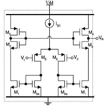
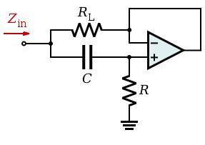
V2 = + input
V1 = - input
The opAmp you are planning to use will have to sink current from the RL resistor, what you trying to use is really an OTA, which usually handles only capacitive loads or very small currents. Unless RL is very large, you should probably add a buffer stage.