Continue to Site

Welcome to EDAboard.com

Welcome to our site! EDAboard.com is an international Electronics Discussion Forum focused on EDA software, circuits, schematics, books, theory, papers, asic, pld, 8051, DSP, Network, RF, Analog Design, PCB, Service Manuals... and a whole lot more! To participate you need to register. Registration is free. Click here to register now.

Op Amp Circuit Question

Status
Not open for further replies.

sr_sample

Newbie level 4
Joined
Aug 30, 2009
Messages
6
Helped
0
Reputation
0
Reaction score
0
Trophy points
1,281
Location
us
Activity points
1,329
op amp circuit

Hello,

Does anyone know how this circuit work? I am having some dificulties understanding it. It looks like an integrator. The Vref is fixed at 2.5V and Vchange can be anything from 0-5V.

What is the equation for the output voltage of the op amp (Vout)?

Thanks,
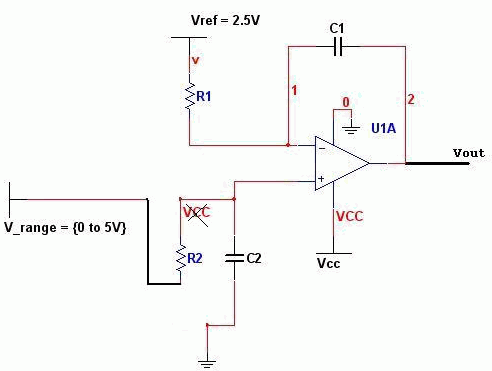
 

circuit question

Is there any circuit diagram with this post ?
 

differential integrator op amp

Sorry I forgot to post the picture. I also figured out the answer between the time I posted and now. But i'll post the pic for discussion purposes.

Thanks,
 

op-amp circuit

With a correction, it's a differential integrator. A shown, R2/C2 are functionless and the transfer function is Vout = 1 + a∫Vin dt.
 

integrating op-amp questions

I think it is a comparator. It would be a differential integrator if both resistors were fed to a different voltage source. It is a comparator that ramps to 0 or Vcc depending on the relative difference between Vref and Vrange. The ramp rate is determined by R1 and C1.

So if:

Vrange < Vref

The output will ramp from Vrange to 0

If: Vrange > Vref,

The output will ramp from Vrange to Vcc.


The circuits ramps up or ramps down, but it does not integrate as the classical integrator.
 

question on opamp circuits

A difference between Vin and Vref is also a difference between two input voltages. But you can regard it as noninvrting integrator as well.

Here's the correction. The circuit is working as integrator if R1•C1 = R2•C2

15_1251666413.gif
 

ramp op amp

Yes I agree. The modified picture that you posted is a difference integrator. I am using the original post as a method to slowly turn off a device under over voltage conditions.

Thanks.
 

op amp circuits question and answer

Yes, it looks like an integrator (called BTC integrator, Balanced Time Constants).
However, I am afraid it will not work because of the single supply voltage.
 

Status
Not open for further replies.

Similar threads

Part and Inventory Search

Welcome to EDABoard.com

Sponsor

Back
Top