Continue to Site

Welcome to EDAboard.com

Welcome to our site! EDAboard.com is an international Electronics Discussion Forum focused on EDA software, circuits, schematics, books, theory, papers, asic, pld, 8051, DSP, Network, RF, Analog Design, PCB, Service Manuals... and a whole lot more! To participate you need to register. Registration is free. Click here to register now.

one side of IR2110 full bridge mosfets burns instantly

Status
Not open for further replies.

farid72j

Junior Member level 3
Joined
Jul 29, 2021
Messages
26
Helped
0
Reputation
0
Reaction score
0
Trophy points
1
Activity points
208
I have build a full bridge inverter using 2 IR2110 and 4 irf840 or 20n60 mosfets. pwm frequency of high side is 18 kHz and for the low side i use 50 Hz pulse. the circuit works fine with 25 and 50 volt from dc supply.
the problem is when i connect 310 v dc of rectifying 220 v ac to the circuit, 2 mosfet on one side burns instantly.

i use different mosfets and dead time up to 2 ms, the result is the same.
can someone tell me where is the problem?
thank you in advance.
 

Attachments

  • SinaInverterPureSineWave.png
    SinaInverterPureSineWave.png
    180.6 KB · Views: 350

IR2110 possibly breaking down (not meeting its max specs) ? But still operational at
lower V.....

Scope capture qualified to trigger when both mosfets are on to possibly capture
event, while also capturing gate drive and source/drain conditions.

MOSFETs have gate to source/drain short ? Or just source/drain lead open or shorted,
another clue.


Regards, Dana.
 
please ignore Brad's comment above - but check the diodes you are using UF4007 - if they are not really 1kV this will cause issues - better to series 2 x 600V e.g. BYV26C
 

If you series diodes you need to equalize them with paralleled resistors so V is equally shared ?


Regards
 

No - they'll be fine as the total rail is < 600V - resistors are a very BAD idea in this application - can you see why danadakk ?

also - check all your fets prior to power up to make sure they aren't short - but it is very easy to kill the IR2110 if the layout is too open and the mid point of the totem pole of fets goes negative, you need some film/foil caps right across the totem poles.
 

I think when Q1 conducts you want 310V to appear at the node between Q1 & Q2.
(At the same time Q4 provides a path to ground.)
So I think you want Q1 source terminal (the more negative terminal because it's N-device) to be at 310V at those times in the cycle.

Therefore bias voltage to Q1 must be greater than the source terminal, in order to fully turn on Q1. So bias voltage must go to greater than 310V.

However I have no experience with mosfet driver IC's and IR2110 may supply correct bias voltages for all I know. It's not readily obvious looking at the schematic.
 

Hi

High-side drive voltage.
For sure the high side drive voltage is greater than 310V ... referenced to GND.
But reference to GND does not count here.

Reference to the Mosfet's SOURCE does count (V_GS = voltage between GATE and SOURCE)
With a bootstrap circuit this will always be between 0V (OFF) and 12V (ON)
(Indeed 12V minus diode drop minus a bit else)

Klaus
 

No - they'll be fine as the total rail is < 600V - resistors are a very BAD idea in this application - can you see why danadakk ?

also - check all your fets prior to power up to make sure they aren't short - but it is very easy to kill the IR2110 if the layout is too open and the mid point of the totem pole of fets goes negative, you need some film/foil caps right across the totem poles.
ir 2110 is fine. cause mosfet burns instantly and i unplug the circuit. after changing the mosfets, i test the circuit with low voltage and it works fine.

i didn't quiet understand what you said about totem pole goes negative, can u explain more?
 

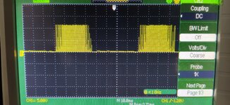
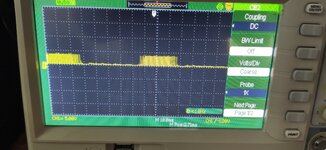
today i saw something strange. after connecting mosfet supply, VGS of high side mosfets drops significantly (down to 3 volts), and its noisy.
but the output signal is fine.
what may the reason be?
--- Updated ---

IR2110 possibly breaking down (not meeting its max specs) ? But still operational at
lower V.....

Scope capture qualified to trigger when both mosfets are on to possibly capture
event, while also capturing gate drive and source/drain conditions.

MOSFETs have gate to source/drain short ? Or just source/drain lead open or shorted,
another clue.


Regards, Dana.
Hi Dana. thank you for your quick response.
I checked two mosfets that was burned last time. one of them has gate to source and gate to drain shorted and the other just has shorted gate to source.
can you explain what happened here?
 

Attachments

  • IMG_20210802_144642.jpg
    IMG_20210802_144642.jpg
    4.2 MB · Views: 110
  • IMG_20210802_144705.jpg
    IMG_20210802_144705.jpg
    3.6 MB · Views: 96
Last edited:

Sure sounds like body diode in MOSFETs not fast enough and you are exceeding Vgsmax
and rupturing gate oxide inside MOSFET. Its ~ worst case 1 uS for internal diode.

Maybe try some ultrafast diodes in parallel with the internal body diode, something on
the order of 100 nS Trr.

You might replace load in bridge with just a R rated for approximate current levels and using
a scope verify no layout problems causing unexpected transients. Use scope triggering to capture
out of spec transients on Vgs. Then try some ultrafast diodes and L load.....

There are people here much more experienced in inverters than me, so take my advice with a
gain of salt.....


Regards, Dana.
--- Updated ---

Question, when you power up is it sequenced to make sure you
have control of the bridge, all MOSFETs off as supply ramps up to spec ?
Especially PWM is not started until processor has control.......


Regards, Dana.
 
Last edited:

Sure sounds like body diode in MOSFETs not fast enough and you are exceeding Vgsmax
and rupturing gate oxide inside MOSFET. Its ~ worst case 1 uS for internal diode.

Maybe try some ultrafast diodes in parallel with the internal body diode, something on
the order of 100 nS Trr.

You might replace load in bridge with just a R rated for approximate current levels and using
a scope verify no layout problems causing unexpected transients. Use scope triggering to capture
out of spec transients on Vgs. Then try some ultrafast diodes and L load.....

There are people here much more experienced in inverters than me, so take my advice with a
gain of salt.....


Regards, Dana.
sorry i forgot to update the schematic. i used 4 uf4007 in parallel with mosfets and yet result was as mentioned before.
to my knowledge body diodes are for reverse current after turning off the circuit, yes?
but i never got to that part and mosfets burns instantly when their supply plugs in!!
 

Hi,

I guess UF4007 is in the range of MOSFET body diode voltage drop. If so, then the body diode still becomes conductive. This should be avoided with the external diode.

Body diodes are not especially designed in, they automatically happen when MOSFETs are produced.

Klaus
 

Hi,

I guess UF4007 is in the range of MOSFET body diode voltage drop. If so, then the body diode still becomes conductive. This should be avoided with the external diode.

Body diodes are not especially designed in, they automatically happen when MOSFETs are produced.

Klaus
Hi
what do you mean external diode? UF4007 is external diode, and i connected them from source to ground of each mosfet.
 

Hi,

Yes. There is the MOSFET and it´s "unavoidable" internal body diode.
The body diode usually is slow.
Thus you need an external diode to prevent the internal, slow one from becoming conductive.

Thus the external diode V_fwd should be smaller than the MOSFET internal body diode´s V_fwd.

Klaus
 

The IRF840 Vishay worst case body diode is 2V max for threshold at 8A.

The UF4007 max is 1.7V at 1 A.

So its questionable if the UF4007 is dominant. But it is fast for sure at 75 nS at 1A.

You could set up a quick bench jig to test the presence and absence of the UF4007
by turnoff off L load on just one MOSFET switching the L load. To see what impact it
actually has. But better diode selection I would think is in order. Note this is a bit
of a crapshoot as body diodes are so poorly speced in datasheets to get a handle
on device to device variation.


Regards, Dana.
--- Updated ---

sorry i forgot to update the schematic. i used 4 uf4007 in parallel with mosfets and yet result was as mentioned before.
to my knowledge body diodes are for reverse current after turning off the circuit, yes?
but i never got to that part and mosfets burns instantly when their supply plugs in!!
Yes on turnoff question.

Burnup when supply plugs in, sure sounds like a power sequencing issue in play here.
You could use a f() gen with ramp and a power pass transistor to ramp supply, and do
a scope capture triggered by say 2V to get an idea of whats going on in circuit. Scope
should have a deep enough memory to do it, depending on sampling rate you choose.


Regards, Dana.
 
Last edited:

Hi,
But it is fast for sure at 75 nS at 1A.
Both diodes should be fast at turn ON. This is not the problem.
The problem is turn OFF.

Reverse recovery time is...
Let´s assume there is reverse current through the MOSFET, thus the body diode becomes conductive.
But the problem is: it stays conductive for a short time even when voltage is reversed.

For a single low side or high side MOSFET this is not the problem, the dides usually never become conductive.

But in a half bridge...(example: Low side PWM while HIGH side is always OFF)
* let´s assume the LOW side is ON.
* then Low side is switched OFF
* due to some load side inductance the HIGH side MOSFET´s body diode becomes conductive
* if you now switch ON the LOW side MOSFET again, then you have the situation that the high side body diode stays conductive while the low side MOSFET is conductive too. --> very high current peak for a short time until the high side body diode releases.
(+supply --> high side diode (reverse) --> low side MOSFET --> GND)

Klaus
 

Status
Not open for further replies.

Part and Inventory Search

Welcome to EDABoard.com

Sponsor

Back
Top