Welcome to our site! EDAboard.com is an international Electronics Discussion Forum focused on EDA software, circuits, schematics, books, theory, papers, asic, pld, 8051, DSP, Network, RF, Analog Design, PCB, Service Manuals... and a whole lot more! To participate you need to register. Registration is free. Click here to register now.
You will need to tell us more about your project.
Do you want to implement the 'deadband' in software or in hardware? What output switching device are you controlling? What output would you expect to see during the 'deadband' ?
Very simply, when the input value is above the high threshold value, you set the output to state A. When the input value is below the low threshold value, you set the output to state C. For other values of input, you are in the 'deadband' and must set the output to state B, but exactly what you do in software will depend on the device you are controlling.
I guess you are not trying to implement hysteresis, which has only two output states.
Ibrahim
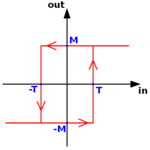
That diagram represents hysteresis, not 'deadband'. You can see that it has only 2 output states: high and low (or M and -M).
Hysteresis is easier to implement in software than a 'deadband'.
The element of code which implements this on an single output requires a variable which holds the current output state ('M' or '-M'). This will only have a logical value of 'on' or 'off', lets call it 'Memory'.
You will also have a numerical input and a logical output (to control the relay).
The input is read regularly in by polling the numerical input. Each time it is read, do the following tests.
When the input value is equal to or greater than M, set the output high and set Memory to 'on'.
When the input value is equal to or less than -M, set the output low and set Memory to 'off'.
When the input value is between -M and M leave the output unchanged (high if Memory is 'on' or low if Memory is 'off')
You will also have to decide what state to use when initialising the output at the start of your code, and set Memory to the corresponding state.
I hope that's clear and that you recognise the difference between 'deadband' and hysteresis.
thank you , i try this code and works well
for loop
mem = PORTE ;
if (input < 50 && (mem =1)) PORTE =0x00;
if ((input > 80) && (mem =0)) PORTE = 0x01;
what do you think about this code ?
This site uses cookies to help personalise content, tailor your experience and to keep you logged in if you register.
By continuing to use this site, you are consenting to our use of cookies.