Continue to Site

Welcome to EDAboard.com

Welcome to our site! EDAboard.com is an international Electronics Discussion Forum focused on EDA software, circuits, schematics, books, theory, papers, asic, pld, 8051, DSP, Network, RF, Analog Design, PCB, Service Manuals... and a whole lot more! To participate you need to register. Registration is free. Click here to register now.

On/off controlled Offline Full Bridge SMPS: EMC problems?

Status
Not open for further replies.

cupoftea

Advanced Member level 5
Joined
Jun 13, 2021
Messages
2,576
Helped
54
Reputation
108
Reaction score
115
Trophy points
63
Activity points
13,530
Hi,
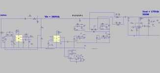
Attached (LTspice and PDF schem) is a 500W offline Full Bridge SMPS in on/off control. Its duty cycle is clamped at just above the max that it would need to be if this was a “normal” full bridge.
Current limit is at the peak needed for max power.
There is no slope compensation as its not needed, even though duty cycle is 0.68.
Would you say there is any reason that this SMPS should fail EMC, compared to a “normal” frequency compensated Full Bridge?
 

Attachments

  • 500W onoff control fullbridge.pdf
    178.8 KB · Views: 125
  • FB 500W 175V_onoff control.zip
    3.1 KB · Views: 92

slope comp is only needed when you are actively trying to set the peak switch current above ~ 24% on time or so. ( 24% of total period )

It is sometimes the case that the slope on the current signal due to Lmag and Lout ( they are in parallel ) provides sufficient feedback to not require slope comp - but needs to be calculated.

The 34% on time provides plenty of dead time ( 26% ) for core self reset - so flux staircasing is not an issue - lucky you.
 
Thanks, yes, i'm actually driving the LT1243 clock pin with a 70% duty signal, so when the output reg comparator trips, then the converter will provide a burst of 70% duty cycle primary "pulses"....until the output reg comparator again trips and shuts it off.....etc etc ad infinitum.....

But as you see, the duty cycle does change drastically within a short space of time at the start and end of a burst....as such, would you agree that a "high side supply type" gate driver will be needed, and not a pulse transformer type high side gate drive?

As you know, pulse transformer type gate drives have series caps which mean they cant handle sudden rapid duty cycle change
 

So, the top post shows a perfectly good 500W offline converter, with a simple feedback loop, and needing no opto in the feedback path, and it has output ripple of just +/-1%.
In the feedback path you just have a digi isolator to pass the comparator signal through to pri side

So is this an absolute revolution in offline SMPS in the making?
 

so flux staircasing is not an issue - lucky you.
I see what you mean...with this "on/off burst mode method", you could in theory, end up with the burst taking the mag current higher and higher with each burst, though as you know, with the schem provided, the mag current will have discharged well down by the time the next burst starts.

Also , another theoretical problem with this approach, is that the power bursts could show up in the mains supply current, (and if loads of them on the mains, could make the mains very on/off if they all "lined up") however, fortunately, the upstream boost pfc output capacitor bank would supply all the bursts, so its ok.

I bet there are gazillions of offline PSUs out there, providing 50mVpkpk ripple, with a frequency compensated, opto coupled feedback loop, when its just a rough dc bus thats needed, and even +/-5% vout ripple wouldnt matter.....the PSU of the top post makes life so much easier.

The SMPS revolution is coming!
 
Last edited:

you need to ensure you meet the flicker specs for on / off operation ...
Thanks, it was thought the upstream PFC and its output capacitor bank would take care of this?
The burst frequency is about 1.2kHz at max load, and as you know, the PFC bandwidth is sub 10Hz.

I know what you mean though, as many such PSU's dont actually have a PFC...though we intend to use one......the attached shows a LTspice sim of a booster followed by the burst-mode PSU of the top post, and none of the burstiness gets through to the source......(i couldnt do a proper PFC sim since as you know it takes too long to settle out).

As such, i believe you would agree....in our case, the flicker issue wont be a problem....since we are using an upstream PFC stage
 

Attachments

  • boost then burster.jpg
    boost then burster.jpg
    138.8 KB · Views: 77
  • booster then FB 500W 175V_onoff control.zip
    4 KB · Views: 78
Last edited:

Status
Not open for further replies.

Similar threads

Part and Inventory Search

Welcome to EDABoard.com

Sponsor

Back
Top