florescent
Member level 1
- Joined
- Mar 9, 2009
- Messages
- 41
- Helped
- 3
- Reputation
- 6
- Reaction score
- 3
- Trophy points
- 1,288
- Location
- The Lone Star, Texas
- Activity points
- 1,677
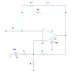
I have a hard time to find a time constant on a relaxation oscillator I have (attached). This is a comparator-based oscillator
I have calculated the transfer function on it. I tried to obtain the time constant from the transfer function, but not easy.
Can anyone help me?
I have calculated the transfer function on it. I tried to obtain the time constant from the transfer function, but not easy.
Can anyone help me?