Continue to Site

Welcome to EDAboard.com

Welcome to our site! EDAboard.com is an international Electronics Discussion Forum focused on EDA software, circuits, schematics, books, theory, papers, asic, pld, 8051, DSP, Network, RF, Analog Design, PCB, Service Manuals... and a whole lot more! To participate you need to register. Registration is free. Click here to register now.

Nport in spectre and sonnet response

Status
Not open for further replies.

omarelmorsy

Junior Member level 1
Joined
May 9, 2022
Messages
17
Helped
0
Reputation
0
Reaction score
0
Trophy points
1
Activity points
145
Hello,
NB: freq desired is @ 27 Ghz
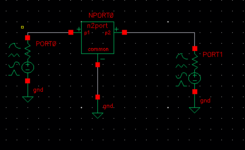
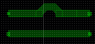
lets say I have a series inductor as shown in image, this inductor consists of 4 ports (1 , -1 and 2, -2) where -1 and -2 are on the lower ground rail to be identified as a ground rail.
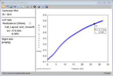
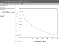
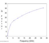
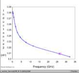
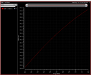
After Emming using sonnet, this produces an s2p file, when I view response on sonnet/cadence plugin it gives me around 220pH for the inductor with a quality factor around 15.

after applying this nport instead of the indq (ideal inductor with series resistance with quality factor 15) as in image 3, the response of the circuit is completely different than what was shown in sonnet response, this problem only arises in series inductor, the grounded or degenerated inductors the response is identical to what was shown in sonnet response.

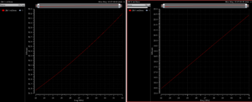
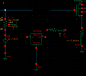
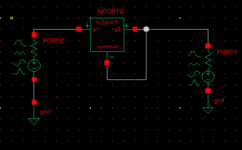
When I test the nport alone on a testbench as in image 4, the seen impedence from port 1 is completely different from what was supposed to appear based on sonnet response it also gave quality factor of around 5 which is completely different from what was shown in sonnet .

one more thing worth mentioning, when I connect the common node to port 2 the results are accurate to what was shown in sonnet as in image 6.

Can any one tell me what am I doing wrong ?
 

Attachments

  • image 1.PNG
    image 1.PNG
    6.8 KB · Views: 110
  • image2.PNG
    image2.PNG
    21.4 KB · Views: 98
  • image3.PNG
    image3.PNG
    8.4 KB · Views: 104
  • image4.PNG
    image4.PNG
    5 KB · Views: 111
  • image5.PNG
    image5.PNG
    33.1 KB · Views: 107
  • image6.PNG
    image6.PNG
    5.5 KB · Views: 103
Last edited:

Your set-up and definitions are not correct.
First, Inductance behavior does not look like an inductor.
Second, return path is also an inductor, How will you define the inductance in this case ? The return path must have zero inductance value so that your inductor may have a meaning.
There are other errors in your circuit and simulation set-up but you have to examine by yourself to find the correct set-up and simulation method.
 

I have also tried to completely remove the ground rail, leaving only the inductor making in this case sonnet make the box walls as the return path for the inductor, the results came out with a certain inductance that was different from what was tested in using the nport using same testbench used above.

Also tested this inductance value vs an indq results are very different.
So problem still exists even when I removed the rail
 

Please post the S-params that you get from this simulation. I want to check shunt capacitance to the substrate.
I have attached the s2p file generated from the inductor with ground rail with ports (-1 and -2)
 

Attachments

  • Full_Layout_test_SonnetEM.rar
    8.5 KB · Views: 91

My mistake, there is no shunt path to substrate included because you have used +/- ports. Your model behaves like pure series path, so extrating the equivalent L and C should work fine and give the same result at that frequency as the S2P block.

But I get Inductance2 and Resistance2 that is different from your plot !?
 

Attachments

  • ind2.PNG
    ind2.PNG
    59.2 KB · Views: 89
  • res2.png
    res2.png
    108.6 KB · Views: 96

My mistake, there is no shunt path to substrate included because you have used +/- ports.

But I get Inductance2 and Resistance2 that is different from your plot !?
This is because I have been editing on the inductor since then trying to figure out the problem, this is the last inductor but with same problem which is having different inductance value and quality factor in the nport than the one measured in sonnet.
Notes:
1) this problem only arises in series inductor, shunt inductors doesn't have this problem.
2) the 50 ohm (in nport results image) of the Zm real is due to port resistance, so real resistance is onle around 2.4 ohm
 

Attachments

  • nport result.PNG
    nport result.PNG
    56.1 KB · Views: 89
  • sonnet L.PNG
    sonnet L.PNG
    37.4 KB · Views: 85
  • Sonnet Q.PNG
    Sonnet Q.PNG
    15.5 KB · Views: 85
  • testbench.PNG
    testbench.PNG
    5.4 KB · Views: 88

You are making it very difficult to support you. I have been in Sonnet support for many years, but it is difficult to get useful information from you.

My guess is that you compared apples to oranges in your calculation. We have seen that S-params that you sent have <1 Ohm series resistance. If you are unable to see that in Cadence, something is wrong there with your setup or math, or you use the wrong data file.

I give up here, sorry.
 

Status
Not open for further replies.

Part and Inventory Search

Welcome to EDABoard.com

Sponsor

Back
Top