Continue to Site

Welcome to EDAboard.com

Welcome to our site! EDAboard.com is an international Electronics Discussion Forum focused on EDA software, circuits, schematics, books, theory, papers, asic, pld, 8051, DSP, Network, RF, Analog Design, PCB, Service Manuals... and a whole lot more! To participate you need to register. Registration is free. Click here to register now.

Not getting the ideal output

Status
Not open for further replies.

varundua

Newbie level 3
Joined
Jun 23, 2015
Messages
4
Helped
0
Reputation
0
Reaction score
0
Trophy points
1
Activity points
38
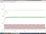
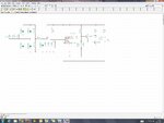
I implemented this circuit and am getting the output desired but what I observe is that if I dont connect anything across the Zener diode (i.e. if I remove everything after the capacitor connected parallel to zener diode) i'm getting a constant a 12V but if I connect everything I dont get a 12V across the Zener voltage regulator, basically there's a voltage drop.

Could you pls help in identifying where I'm going wrong or maybe I have chosen some wrong value of resistor or capacitor somewhere which is causing this drop, because Waveform.jpgUntitled.jpgI need a 12V across the zener voltage regulator when everything is connected.
 

Doesn't look like a reasonable power supply. You have large power dissipation of R1, but still too little current to supply the circuit. It's surely not correctly dimensioned, how doid you arrive at the component values?

People typically use a series capacitor to drop most of the input voltage in a transformerless power supply.
 

Uploading a more readable figure. I'm supplying 230V ac main supply and converting it to 12V. The power dissipation that i calculated comes out 7.078W and so I have now divided it into 8 resistors of equal resistance of 2.55k.

Could you suggest how to implement the series capacitor to drop the voltage?
https://obrazki.elektroda.pl/9156286400_1435050028.jpg

Or maybe what according to you should be an ideal circuit to construct a 1-shot trigger IC555 where the 230V AC voltage is converted to a 12V DC Circuit using a Zener Voltage Regulator?
 
Last edited by a moderator:

The current into the 12 V node must be greater than the current drawn by the connected circuit, LM555 and transistors at 12V. Aparently it isn't, so the zener diode can't regulate.

By the way, the capacitors parallel to the AC source are useless and unwanted.
 

Ok made few more changes and now getting the right output..
https://obrazki.elektroda.pl/2404526100_1435052033.jpg

One last doubt, this circuit would work only if I have a 230V AC Supply but incase if I have a 230V DC Supply, all the DC would get blocked by the capacitor and so we would not get any output. So any chnages that I can make to this circuit so that It works also for a 230V DC?
 

You have the mains L and N going into the bridge and one output of it goes to earth. This will blow the mains fuse or trip the earth leakage breaker. The COM or earth of the electronics must be left floating, which means the whole circuit cannot be connected to any earthed piece of equipment. If your monostable delivers a short pulse you can feed it through a pulse transformer or an optoisolator to the next circuit, BUT all the preceeding circuit must be properly insulated, because the L and N of the mains may be interchanged.
Frank
 

Status
Not open for further replies.

Part and Inventory Search

Welcome to EDABoard.com

Sponsor

Back
Top