Continue to Site

Welcome to EDAboard.com

Welcome to our site! EDAboard.com is an international Electronics Discussion Forum focused on EDA software, circuits, schematics, books, theory, papers, asic, pld, 8051, DSP, Network, RF, Analog Design, PCB, Service Manuals... and a whole lot more! To participate you need to register. Registration is free. Click here to register now.

Noob question (Signal generation)

Status
Not open for further replies.

stowoda

Newbie
Joined
Oct 12, 2009
Messages
2
Helped
0
Reputation
0
Reaction score
0
Trophy points
1,281
Activity points
1,301
Hi there.

I havent work with DSP´s yet and I am wondering about the boundaries
which are given when generating periodical signals with a DSP.

What I know or assume to know is:
- The signal must be represented digitally (inside the DSP)
- It can be fed into the DSP from the outside analogue world via a ADC
- A simple signal form would propably be a sine with parameters like (f,phi,amplitude)

What I would like to know:
- If I am not feeding a analogue signal into the DSP, how could I generate,
for example, a sine. In especially, how would it look like in software?
- I can imagine, that there is a function provided by the compiler that might more or less look like that: Sine(f,phi,Amplitude)
- Can I use mathematical formulas to represent more complex signals?

regards
stowoda
 

Hi Stowoda,

- If I am not feeding a analogue signal into the DSP, how could I generate, for example, a sine. In especially, how would it look like in software?

If you are working in MATLAB, it would look like a sine wave. What else would you expect. What you need is to write a code of 2 to 3 lines, and it will show you the sine wave.

- I can imagine, that there is a function provided by the compiler that might more or less look like that: Sine(f,phi,Amplitude)

May be some compiler has this type of function but this varies from software to software.

- Can I use mathematical formulas to represent more complex signals?

Yes, you can. However, can you please elaborate your question?
 

Hi.


If you are working in MATLAB, it would look like a sine wave. What else would you expect. What you need is to write a code of 2 to 3 lines, and it will show you the sine wave.
Could You show me how the 3 lines of code would look like?

Yes, you can. However, can you please elaborate your question?
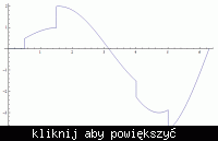
By more complex, for example, I mean something like that:


Mathematically one can describe that using a sine and a shifted Heavyside distribution.

Is that possible?
 

Hello. I am a student and I will work this semester with DSK6416 from TI, I have the same problem as you do. I am struggling for two weeks to get a task done but I can't find the propper solution.
I have to send from Matlab simulink a sinus signal to the board, receive it without any manipulation and then compare the two signals in order to see the distorsions ( FFT, distorsions over frequency, distorsions over power ).
1. How can I send the sinus signal? I only manage to send signal from the MIC or the Line In, I don't have a ADC block for other types of signals
2. How can I see the output results on my monitor?
3. which blocks should i use for the detailed analyse?
I have also tried to do this task with Audiotester software, but I have problems in generating the sinus form over there. Thank you in advance for your help, any answer or other idea is welcomed.
Kind regards,
Vlad
 

Status
Not open for further replies.

Part and Inventory Search

Welcome to EDABoard.com

Sponsor

Back
Top