Continue to Site

Welcome to EDAboard.com

Welcome to our site! EDAboard.com is an international Electronics Discussion Forum focused on EDA software, circuits, schematics, books, theory, papers, asic, pld, 8051, DSP, Network, RF, Analog Design, PCB, Service Manuals... and a whole lot more! To participate you need to register. Registration is free. Click here to register now.

Non zero output from LM358 even though input is zero

Status
Not open for further replies.

Arbit1

Newbie level 5
Joined
Jul 31, 2021
Messages
10
Helped
0
Reputation
0
Reaction score
0
Trophy points
1
Activity points
104
Hi
I was using LM358 as voltage comparator in non inverting configuration
I gave 5V to vcc and 2.5V to inverting pin through a potentiometer
The issue is I am getting a output voltage of approx 3.8V even when the supply to the non inverting terminal is zero

I get output no matter I set the voltage of the non inverting pin zero or less than or more than that of inverting terminal
Also the ic gives the same output when non inverting is given some voltage and inverting is zero

The ic output gets zero only when both inverting and non inverting terminals are zero

Please help me to sort this

I desire to get high output only when the voltage at non inverting is greater than that at inverting i.e 2.5V
1632258769160.png
 

Either the LM358 device is defective, or there's something wrong with your circuit. The reported behaviour doesn't comply with known device behaviour.

I'd prefer a complete circuit diagram, including VCC and GND pins.
 

Beware of phase reversal problems if your input violates CM range
at its inputs.


And some latchup until power removed -


Regards, Dana.
 

Hi,

A comparator is a comparator,
An Opamp is an Opamp.

There's a good reason why there are two different types. Both with different requirements and different operation conditions.
Sadly they share the same schematic symbol.
And sadly many posts of hobbyists misuse the one for the other function.

In some cases it may work. But in many cases there will be problems.

Thus I generally recommend to use the correct device for the correct function.
**
In opposite to a simulation a real opamp and comparator circuit needs power supply stabilizing capacitors.
******

You tell about the inverting input.
But you don't tell about the noniverting input, the output circuitry and the power supply circuitry.

Thus - as FvM already wrote - we need to see the whole story.

Klaus
 

You must define your input and output expectations and don't use an LM358 as a comparator (a.k.a. limiter, slicer, level shifter) unless you do not exceed all the constraints in the datasheet and don't care about Voh.

Start with expectations, consider CMOS inverter as a crude but fast rail-to-rail Vdd/2 "signal slicer" Use the 4000 series CMOS with resistor feedback and AC coupled also works with care on RC =T

But if you want precision. read the datasheets until you understand what fits your expectations or "specs" and never make assumptions that all your connections are OK until probed.
 

According to post #1, the OP was operating inside CM range. LM358 doesn't expose phase reversal, respectively as long as one input is within common mode limits, you'll see the expected output voltage according to input difference voltage sign.

Many things said in this thread are correct in principle, but don't actually apply to the reported case. There's e.g. nothing against using LM358 as comparator if you are satisfied with its speed.
 

Hi,
as long as one input is within common mode limits, you'll see the expected output voltage according to input difference voltage sign.
Are you sure?
I always thought that if one input is outside CMIR then the whole difference input stage (both emitter) current may drop to zero and thus the output state is undetermined.

Many things said in this thread are correct in principle, but don't actually apply to the reported case. There's e.g. nothing against using LM358 as comparator if you are satisfied with its speed.
I agree. No phase reversal. And if you are correct with the CMIR then it should work as comparator. Low speed, maybe unsymmetries in timing and levels....
I even saw in some (mature) OPAMP datasheets application schematics where they use them as comparators.

**

I repeatedly remind about the difference between OPAMPs and comparators, especially for the unexperienced members. They should know that only some OPAMPS can be used as comparators ... but many OPAMPs are not suitable. And that they have to expect reduced performance.
(it´s the same the other way round)

***

I had to learn it the hard way: I designed (in my early electronics days) a circuit that protects speakers against DC. At a dedicated DC threshold they should switch OFF a relay. So far so good.
I tested it and it worked ... for low DC voltages. I didn´t think about testing at high DC voltages.
But then one day ( I tested a self made audio amplifier) a fuse blew and high DC voltage was on the speaker. The relay switched OFF ... but only for much less than a second .. and due to phase reversal of the OPAMP the relay switched ON again. My really expensive bass speakers got damaged.
I studied what caused the problem. And from this time on I think I never used am OPAMP as comparator anymore.

Klaus
 

OP LM358 and comparator LM393 have similar input stages with same static characteristic, the latter with an additional circuit to speed-up dynamic large signal behavior

1632296898336.png
1632296850561.png
 

Hi,

thank you for the schematics.
Now I see the 6uA current source (left picture) still will work when one input is close to VCC.
Makes sense.

Klaus
 

I replaced the opamp with LM393

The issue is when I test the comparator individually ,it works fine, i.e it will give output only when noninverting is greater than inverterting

But when I connect it in the whole circuit the same issue occurs of giving output when noninverting is zero

PLEASE HELP ME TO SORT IT

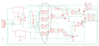
The four comparators marked in the circuit have issue
 

Attachments

  • forumbs.png
    forumbs.png
    22.4 KB · Views: 87

I get a sim that makes sense. Note I have swept Inv input > 3V which violates input
CM range, but datasheet seems to convery as long as one input in CM range all is good.

1632397437756.png


1632397065339.png


Regards, Dana.
 
Last edited:

I replaced the opamp with LM393

The issue is when I test the comparator individually ,it works fine, i.e it will give output only when noninverting is greater than inverterting

But when I connect it in the whole circuit the same issue occurs of giving output when noninverting is zero

PLEASE HELP ME TO SORT IT

The four comparators marked in the circuit have issue
List all the voltages on each pin during this fault condition
--- Updated ---

Design fault appears to be pin 3 is grounded on both IC1,2 .
1632399450840.png


Also diode in FET does not protect it from flyback coil very high +ve voltage spike on turnoff. You must add reverse voltage diode across each coil. Do this 1st.

Also Q1 - C5 junction is floating and depends on parasitic leakage and input bias current. Bad choice of integrator. No need for Q1 if R3 is in series from IC3A-p3
 
Last edited:

Hi,

I agree with SunnySkyGuy.

The schematic is a mess. It contains drawing mistakes, schematic mistakes, missing informations...
This makes it hard for us to understand the function ... and the problem.
If you want we can discuss about them. (way more than 10 issues)

What software are you using? Did you run an ERC?

Klaus
 

Last edited:

Might be Eagle schematic. It has these famous hidden supply pins in some libraries.
Anyway, come back with a schematic that shows all IC connections including supplies.
--- Updated ---

I checked with an old Eagle version. You can manually add supply pins either to A or B symbol with Invoke command. Or connect implicite supply pins, but I would strongly discourage doing so.
--- Updated ---

As mentioned by KlausST, simply pressing ERC shows all missing pin connections.
 
Last edited:

Hi,

If the circuit is real or simmed, use an oscilloscope to see if it is oscillating. May need hysteresis.
--- Updated ---

Hi again,

According to the 2V to 36V LM393 datasheet section called '8.2.2.1 Input Voltage Range', and if your Vref is only 2.5V, and the supply voltage is 5V, that shouldn't happen as common-mode range is 0V to Vcc -1.5V and you don't seem to violate any of the rules in that section of the datasheet. Could be that no decoupling/bulk capacitors on the comparators' supply pins drags the supply voltage down when the comparators switch from high to low and that droop shifts Vref as they live on the same supply line, but I doubt that is the problem. Vref isn't static, by the way it moves a little bit when the comparator switches, from what I remember.

If you are simulating this, see if you can do a transient analysis or whatever it's called in your program and look at the signals on a couple (or ideally all four) of the comparator In+ and In- and their Output pins, and on the supply line. Everyone has a favourite simulating tool, I use the free version of the TI one - once you get used to it, it's easy to use and you can look at lots of signals in one transient, and it has a great habit of getting stuck/slowing down a lot with comparator circuits that are oscillating so you know very quickly what the problem is.

Great hint: Spaghetti wiring is bad, replacing it with meaningfully-named jumpers is good.

If you are doing this on a breadboard, I strongly suggest (if you haven't already), taking a deep breath and becoming un-angry and un-confused at the non-functioning circuit, then getting a piece of paper and a pen, and drawing the circuit you actually have on the breadboard by following your connections one by one and checking each twice to make sure the breadboard isn't playing tricks on you such as a wire/connection not where you thought it was - frustrating and maddening minutes to hours can be spent with gremlins like that.

As mentioned, you should say what value the pull-ups are, what Vref is, show any decoupling capacitors on the regulators and the ICs. And what's on the other side of that connector.

Hope you've already solved the issue.
 
Last edited:

Status
Not open for further replies.

Similar threads

Part and Inventory Search

Welcome to EDABoard.com

Sponsor

Back
Top