Continue to Site

Welcome to EDAboard.com

Welcome to our site! EDAboard.com is an international Electronics Discussion Forum focused on EDA software, circuits, schematics, books, theory, papers, asic, pld, 8051, DSP, Network, RF, Analog Design, PCB, Service Manuals... and a whole lot more! To participate you need to register. Registration is free. Click here to register now.

non-zero ground circuit example and solution

Status
Not open for further replies.

vikramc98406

Full Member level 1
Joined
Nov 30, 2007
Messages
97
Helped
8
Reputation
16
Reaction score
6
Trophy points
1,288
Activity points
1,939
Hi,

Can any one point me some examples to circuit examples/solutions where
reference ground is non-zero volt.

Pls refer me any book to go through.

Example query:
------------10ohm----(+) (B)

5v -------15ohm------------(A) 20

-----------10ohm------ (-) (C)


Any understanding how to get Voltage at (A)

Node (B) and Node (C) are not grounded.
Thanks in advance

---------- Post added at 08:14 ---------- Previous post was at 08:12 ----------

re-drqsing the circuit; as it is scrambled in the prev post
Example query:
#######################------------10ohm----(+) (B)
|
5v -------15ohm------------(A) 20
|
#######################-----------10ohm------ (-) (C)


Any understanding how to get Voltage at (A)

Node (B) and Node (C) are not grounded.
 

Your circuit is not very clear. However, the voltage is defined as potential difference between two nodes, so if you want to measure a voltage in A you must specify with respect to which other node ? The same for the applied voltage. Your 5V generator is not clear to which two nodes is connected.
The ground is used just a reference and is arbitrary put to a potential (not a voltage) = 0. Then if you have two nodes X and Y the voltage will be V = potential(X)-potential(Y) if I take Y as ground then potential(y) = 0. then V = potential(X). Since voltage is a relative measurement I can arbitrary set potential(X) or potential(Y) to any value I want. I can do this just for a single node of a network.
 

albbg,


Let me explain the circuit in simple text.

Circuit looks like a 3-legged star network


Node (A) at center

Connection of one leg
5v -> 15ohms -> (A)

Connection of second leg
(A)-> 10ohms-> (B)

Connection of third leg
(A) -> 10ohms -> (C)

5v negative terminal is grounded
potential difference b/w (B) and (C) is 20v

(B) and (C) are not grounded

Question:
Voltage at (A)
 

I fear, the question can't be answered, because the description is complete. What is causing the potential difference between (B) and (C)? There must be additional circuit elements.

If you mean, that there are additional sources, but none is connected to ground/5V, then the problem is trivial, and you should be able to answer it yourself.
 

albbg,


Let me explain the circuit in simple text.

Circuit looks like a 3-legged star network


Node (A) at center

Connection of one leg
5v -> 15ohms -> (A)

Connection of second leg
(A)-> 10ohms-> (B)

Connection of third leg
(A) -> 10ohms -> (C)

5v negative terminal is grounded
potential difference b/w (B) and (C) is 20v

(B) and (C) are not grounded

Question:
Voltage at (A)
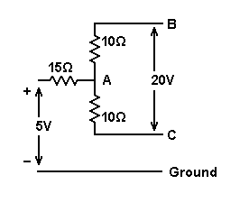
So the circuit is like this:

eda1.gif


Voltage at (A) with respect to what? i.e. if one probe of the voltmeter is connected to point (A), to what is the other probe of the voltmeter connected?
 

Syncopator,

the circuit drawn by you is correct

Question is:
Voltage at (A) w.r.t ground.


PS: Pls let me know how did you draw the circuit, so that i can explain easily next time
 

Question is:
Voltage at (A) w.r.t ground.


The voltage at A w.r.t. ground is 5 volts.
Explanation: V(B)=+15 volts and V(C)=-5 volts; therefore: V(A)=5 volts (50% of the median value).
Another explanation: There is no current through the 5 volts source.
 

Syncopator,

the circuit drawn by you is correct

Question is:
Voltage at (A) w.r.t ground.

LvW has given you the answer.


PS: Pls let me know how did you draw the circuit, so that i can explain easily next time

I use Microsoft's Paint.

I have made up a small library of symbols. Would you like it? It might save you time if you want to try that method.

It's quite easy to use. You can select bits of the various symbols or drawn items, copy and paste them.
 

Status
Not open for further replies.

Similar threads

Part and Inventory Search

Welcome to EDABoard.com

Sponsor

Back
Top