Continue to Site

Welcome to EDAboard.com

Welcome to our site! EDAboard.com is an international Electronics Discussion Forum focused on EDA software, circuits, schematics, books, theory, papers, asic, pld, 8051, DSP, Network, RF, Analog Design, PCB, Service Manuals... and a whole lot more! To participate you need to register. Registration is free. Click here to register now.

Non-Inverting Amplifier (AC Coupled) : How to solve this circuit with lower and high frequency?

Status
Not open for further replies.

Dragnovith

Junior Member level 1
Joined
Apr 17, 2021
Messages
17
Helped
0
Reputation
0
Reaction score
0
Trophy points
1
Activity points
104
I need to design this circuit with a gain of 26 for signals where the frequency varies from 800Hz to 8kHz and I also need to find out the current on the RL load. (VA = 100mV)
Will C1 behave like an open circuit in ac analysis?
I am getting to lower the frequency (800Hz) but I am not able to project to the frequency of 8kHz. Regarding the current I have a little doubt if it will be only 2.5 V divided by the RL.
circuitopamp.jpg
 

C1 is not an open circuit; its impedance depends on frequency.

i don’t know what you mean by “...I am not able to project to the frequency...”

The current in the load will be 2.6(not 2.5) /RL.

Your opamp power supplies are backwards.
 
Hi,

You want to amplify frequencies 800Hz ... 8000Hz. I guess this is homework.

So
* frequencies below 800Hz need to be supressed, or in other words: higher frequencies than 800Hz need to pass --> High pass filter, HPF
* frequencies obove 8000Hz need to be supressed --> lower frequencies than 8000Hz need to pass --> Low pass filter, LPF

Do a quick search in your schoolbook how to design HPF and LPF (hardware, schematic) and how to calculate fc or part values.
Internet is also full of those informations: descriptions, explanations, online calculators, tutorials, even video tutorials.

In your schematic there are capacitors. All are involved in filter circuits, all of them are high pass filters. No low pass filter.
Thus it's no wonder that you don't get the 8000Hz thing to work. --> correct your schematic.

Remarks about the schematic:
* Don't remove part names. "The upper resistor of the two marked with 'R' " is a rather difficult description. While "R1" is easy and clear.
* add values you already know or you already have calculated, so we can check if you did it right.
* the text says "VA", but "VA" is not in your schematic. So it's not clear whether you mean V1 or VAC, VAverage, VAmplifier or anything else..

You want to know current of RLoad.
There are many "current for RLoad": IAverage, IRMS_including DC, IRMS_excluding DC, poitive peak, negative peak, peak to peak....
Since you are interested in frequency response, you need to tell the input frequency and the input waveform.
Frequency as well as waveform determines IRLoad.

Some details. (Solve the other thing first before focussing on them)
* A filter is not a ON/OFF thing. It is not: gain of 0 at 799Hz and not gain of 26 at 801Hz.
An RC filter first order will show gain of 26/sqrt(2) at fc = 800Hz.

* If you add multiple filters high pass filters in series each desinged for fc= 800Hz, then the resulting fc will be higher than 800Hz.

* If you add a 800Hz HPF, a 8000Hz LPF and a gain stage of 26, then the maximum overall gain never reaches 26, I rather guess about 23.5 close at sqrt(800Hz x 8000Hz).

**********
A real circuit needs power supply decoupling capacitors.
I recommend to add them at the simulation schematic ... just to not forget them when you build the real circuit.

Klaus
 
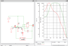
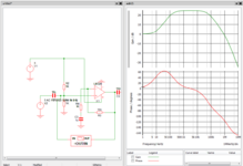
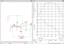
The OpAmp stage exhibits a LPF and HPF characteristic (BPF), in this case LPF cause d by non ideal OpAmp
GBW limitation. But problem appears to stipulate OpAmp is "ideal"....eg. infinite GBW

1618655931972.png


Total response -

1618656574236.png

Regards, Dana.
 

Attachments

  • 1618655878034.png
    1618655878034.png
    93.6 KB · Views: 80
  • 1618656436589.png
    1618656436589.png
    82.5 KB · Views: 78
  • 1618656498914.png
    1618656498914.png
    83.3 KB · Views: 93
Last edited:

The OpAmp stage exhibits a LPF and HPF characteristic (BPF), in this case LPF cause d by non ideal OpAmp
GBW limitation. But problem appears to stipulate OpAmp is "ideal"....eg. infinite GBW

View attachment 168887


Total response -

View attachment 168890
Regards, Dana.
Right, I had managed to reach the frequencies but the gain was wrong, I had also changed the GND and Vdd of op amp. Thanks

how will the transfer function of this circuit be?
--- Updated ---

Hi,

You want to amplify frequencies 800Hz ... 8000Hz. I guess this is homework.

So
* frequencies below 800Hz need to be supressed, or in other words: higher frequencies than 800Hz need to pass --> High pass filter, HPF
* frequencies obove 8000Hz need to be supressed --> lower frequencies than 8000Hz need to pass --> Low pass filter, LPF

Do a quick search in your schoolbook how to design HPF and LPF (hardware, schematic) and how to calculate fc or part values.
Internet is also full of those informations: descriptions, explanations, online calculators, tutorials, even video tutorials.

In your schematic there are capacitors. All are involved in filter circuits, all of them are high pass filters. No low pass filter.
Thus it's no wonder that you don't get the 8000Hz thing to work. --> correct your schematic.

Remarks about the schematic:
* Don't remove part names. "The upper resistor of the two marked with 'R' " is a rather difficult description. While "R1" is easy and clear.
* add values you already know or you already have calculated, so we can check if you did it right.
* the text says "VA", but "VA" is not in your schematic. So it's not clear whether you mean V1 or VAC, VAverage, VAmplifier or anything else..

You want to know current of RLoad.
There are many "current for RLoad": IAverage, IRMS_including DC, IRMS_excluding DC, poitive peak, negative peak, peak to peak....
Since you are interested in frequency response, you need to tell the input frequency and the input waveform.
Frequency as well as waveform determines IRLoad.

Some details. (Solve the other thing first before focussing on them)
* A filter is not a ON/OFF thing. It is not: gain of 0 at 799Hz and not gain of 26 at 801Hz.
An RC filter first order will show gain of 26/sqrt(2) at fc = 800Hz.

* If you add multiple filters high pass filters in series each desinged for fc= 800Hz, then the resulting fc will be higher than 800Hz.

* If you add a 800Hz HPF, a 8000Hz LPF and a gain stage of 26, then the maximum overall gain never reaches 26, I rather guess about 23.5 close at sqrt(800Hz x 8000Hz).

**********
A real circuit needs power supply decoupling capacitors.
I recommend to add them at the simulation schematic ... just to not forget them when you build the real circuit.

Klaus
Yes,
Hi,

You want to amplify frequencies 800Hz ... 8000Hz. I guess this is homework.

So
* frequencies below 800Hz need to be supressed, or in other words: higher frequencies than 800Hz need to pass --> High pass filter, HPF
* frequencies obove 8000Hz need to be supressed --> lower frequencies than 8000Hz need to pass --> Low pass filter, LPF

Do a quick search in your schoolbook how to design HPF and LPF (hardware, schematic) and how to calculate fc or part values.
Internet is also full of those informations: descriptions, explanations, online calculators, tutorials, even video tutorials.

In your schematic there are capacitors. All are involved in filter circuits, all of them are high pass filters. No low pass filter.
Thus it's no wonder that you don't get the 8000Hz thing to work. --> correct your schematic.

Remarks about the schematic:
* Don't remove part names. "The upper resistor of the two marked with 'R' " is a rather difficult description. While "R1" is easy and clear.
* add values you already know or you already have calculated, so we can check if you did it right.
* the text says "VA", but "VA" is not in your schematic. So it's not clear whether you mean V1 or VAC, VAverage, VAmplifier or anything else..

You want to know current of RLoad.
There are many "current for RLoad": IAverage, IRMS_including DC, IRMS_excluding DC, poitive peak, negative peak, peak to peak....
Since you are interested in frequency response, you need to tell the input frequency and the input waveform.
Frequency as well as waveform determines IRLoad.

Some details. (Solve the other thing first before focussing on them)
* A filter is not a ON/OFF thing. It is not: gain of 0 at 799Hz and not gain of 26 at 801Hz.
An RC filter first order will show gain of 26/sqrt(2) at fc = 800Hz.

* If you add multiple filters high pass filters in series each desinged for fc= 800Hz, then the resulting fc will be higher than 800Hz.

* If you add a 800Hz HPF, a 8000Hz LPF and a gain stage of 26, then the maximum overall gain never reaches 26, I rather guess about 23.5 close at sqrt(800Hz x 8000Hz).

**********
A real circuit needs power supply decoupling capacitors.
I recommend to add them at the simulation schematic ... just to not forget them when you build the real circuit.

Klaus
VA refers to V1, My mistaken, sorry.

The current is the current that passes there in that resistor.

Wouldn't the high pass filter be that capacitor with the resistor at the end?
By adjusting it, I was getiing to limit the higher frequency.

I think I need to find the transfer function of the circuit to find the appropriate values for the resistors. But I'm having difficulties to find the function.

Thanks
 
Last edited:

Hi,
The current is the current that passes there in that resistor.
Every of the obove mentioned currents may (will) pass the resistor. .
Some may not exist in "ideal" circuits, but will in real circuits.

Wouldn't the high pass filter be that capacitor with the resistor at the end?
You may use the partnames given in the schematic to clearly address one capacitor. (C1, C2, C3)

As already mentioned every of your three capacitors act as HPF capacitor.
The problem is: There is no LPF. No circuit that limits upper frequency. ( 8000Hz)


Klaus
 
You can always consider using the OpAmps internal freq compensation C to yield a BPF like
response which has of course a LPF characteristic in it- attached

Although part to part variation would be a problem.


Regards, Dana.
 

Attachments

  • ABandpassFilterUsingtheOperationalAmplifierPole.pdf
    262.4 KB · Views: 81
Last edited:
Right, I had managed to reach the frequencies but the gain was wrong, I had also changed the GND and Vdd of op amp. Thanks

how will the transfer function of this circuit be?
--- Updated ---


Yes,

VA refers to V1, My mistaken, sorry.

The current is the current that passes there in that resistor.

Wouldn't the high pass filter be that capacitor with the resistor at the end?
By adjusting it, I was getiing to limit the higher frequency.

I think I need to find the transfer function of the circuit to find the appropriate values for the resistors. But I'm having difficulties to find the function.

Thanks

Transfer function straight forward LaPlace algebraic analysis, use a single pole rolloff model for
internal G element in OpAmp. Excellent tool for this is signal flow graph analysis.


Regards, Dana.
 

Status
Not open for further replies.

Part and Inventory Search

Welcome to EDABoard.com

Sponsor

Back
Top