Continue to Site

Welcome to EDAboard.com

Welcome to our site! EDAboard.com is an international Electronics Discussion Forum focused on EDA software, circuits, schematics, books, theory, papers, asic, pld, 8051, DSP, Network, RF, Analog Design, PCB, Service Manuals... and a whole lot more! To participate you need to register. Registration is free. Click here to register now.

Noise Figure in Very Low IF (VLIF) receiver

Status
Not open for further replies.

alberto.fuggetta

Newbie level 3
Joined
May 8, 2010
Messages
4
Helped
0
Reputation
0
Reaction score
0
Trophy points
1,281
Location
Italy
Activity points
1,321
Hi,

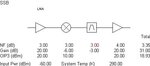
I'm in the system level design stage of a very low IF receiver (VLIF).
Simulating the chain in ADS I get a SSB noise figure that is 3 dB higher than the corresponding Direct Conversion Receiver (DCR).
This is due to the noise at the image frequency. (f_IM = f_RF + 2*f_IF)
I guess I should recover this 3 dB loss somewhere in the receiver chain, otherwise the VLIF architecture would be always disadvantageous.
Does the complex digital mixer do the job?
Thanks a lot,

Alberto
 

Something that can help is an image-reject mixer.
 

Alberto
you are right. Proper recombination of I and Q signals will recover the 3 dB. This is true in low IF systems as well as in image rejection mixers (where recombintion is done in analog domain and usually at higher IF.

Hope it can help.

Mazz
 

Dear Alberto:
Measuring the noise figure of a very low IF receiver can be a challenge. Many RF power meters start only at 10 or 50 MHz. I had the same problem- my task was to test the NF of a mm-wave receiver with ~ 1 MHz IF. I chose a spectrum analyser, HP 8569B; this one has two recordable functions, and amplitude resolution from linear to 1,2,5 and 10 dB/div.
I used a liquid-nitrogen cooled load generating 77 K into receiver RF input; the other noise temperature was ambient, 290K. Then I set the analyzer to read close to zero frequency and up to 10 MHz; with 1-dB resolution I could read and record several runs. I obtained ~ 1 dB change around 1 MHz, so using the Y-factor method, the receiver had ~ 5 dB noise figure.
Many modern spectrum analyzers can do the same; I recommend this method.
 
Thanks for all the answers. In my system, the IF is around 500 kHz and cannot be filtered before the demodulator. For this reason, I would use a digital complex mixer to remove the image.
I simulated my system in Matlab and I actually had the proof the a simple sinusoid at the image frequency is fully removed with no impact on system performance.
However, what I'm still not able to simulate the 3 dB SNR gain after the digital complex mixer.
Why do I only have the interferer removed while the noise is still there?

Thanks
 

Dear Alberto:

noise figure of any receiver must be measured on the LINEAR receiver section, no detectors or demodulators allowed.
You also only talk about simulation, I work with real stuff only.
You can remove or rather suppress interferers but noise cannot be removed. Receiver noise is primarily caused by the first stages, then amplified. This is why the first stages are important in low-noise receiver design.

I do not see any reasonable meaning in your expression "3 dB SNR gain". SNR is the signal-to-noise ratio, gain is not linked to it.
On a real receiver, you can leave both sidebands and measure the DSB noise figure. If you suppress the undesired sideband, you have to add 3 dB to the measured noise figure as it became SSB noise figure.
 

I think the mechanism behind is the same as a image reject mixer.
In that case DSB and SSB noise figure are almost the same. Am I wrong?
What I'm trying to prove is that my system has same NF of a direct conversion receiver where there are no image noise problems.
Thanks.

Alberto
 

Dear Alberto:

The difference between DSB and SSB noise figures is 3 dB. If no filter is used to reject the "undesired" sideband, then both sidebands are translated into the IF band. This means twice the noise power (3 dB) is converted as the "desired" signal. Such DSB operation is preferred in radiometers that process noise-like wideband "signals".

If you reject the undesired sideband (which is preferred in signal-processing receivers), the SSB noise figure will be 3 dB higher than the above.
Image-reject mixers utilize LO and signal phasing instead of filters; by this they can suppress the undesired sideband quite effectively; such receiver then has the SSB noise figure as only one sideband is used.
 

You don't need to use digital complex mixer, just use such as Hittite image reject mixer, even your IF is only 500KHz. The image reject mixer add one hybrid coupler can reach image reject easily, which had been proven in mathmatic, that is nothing relate with what your IF is.
 

Alberto
you a right when you say that a similar process is behind the image rejection and the DSB/SSB noise difference.
The reason is that noise coming from common part of the receiver (not the one generated by I & Q path) that is usually the dominating one, is correlated, so it is canceled out by proper IQ recombination (that, in your case, should be done in a complex digital IQ mixer).

First, did you check that you have image rejection? How many dBs?
Second, can you show briefly a cascade analisys of the receiver?

I've designed (for large volume products) both image rejection mixers and low IF receiver, and, in both cases they worked as expected.

I hope it can help.

Mazz
 
Mazz,

in my system image rejection should be around 30 dB, just considering the amplitude and phase imbalance of the demodulator.
I used a simple spreadsheet to compute the noise figure using the standard Friis formula with one exception: I added 3 dB noise figure at the cascade noise figure after the demodulator (i.e. I multiplied by two in linear fashion) and then kept using the standard formula for the baseband section.
I end up then with the SSB noise figure. I can extrapolate the final noise figure, just subtracting 3 dB. Am I wrong?
Moreover, the SSB NF I get is different from DSB NF + 3 dB. In other words, if I add 3 dB at the end of the computation I don't get the same result (of course).
In my opinion, adding 3 dB after the demodulator is the right choice. Could you confirm please?
I was not able to find any similar case neither on Razavi nor on Qizheng Gu.

Thanks a lot

Alberto
 

The SSB compare to DSB is make Mixer NF decreasing 3dB. So you can use SysCal (free software) to simulate. I simulate a system with DSB and get system NF 3.39dB, but SSB system NF is 3.35dB, only 0.04dB improve. Of course, different system have different result, it's up to your system.
 

Attachments

  • DSB.JPG
    DSB.JPG
    13.5 KB · Views: 130
  • SSB.JPG
    SSB.JPG
    13.5 KB · Views: 127

Status
Not open for further replies.

Part and Inventory Search

Welcome to EDABoard.com

Sponsor

Back
Top